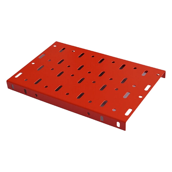
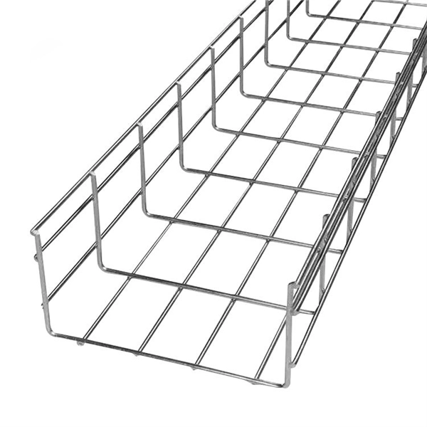
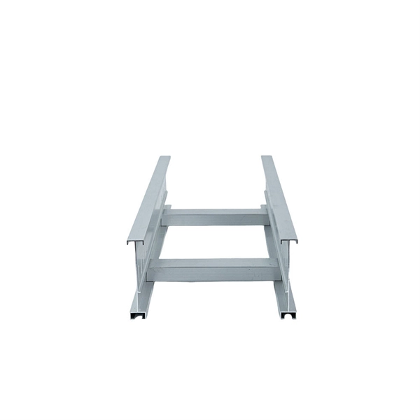
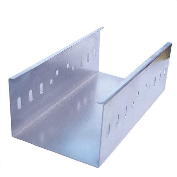
The 1/4"-28 stainless steel cone point machine screw can be tightened to ensure a proper connection when holding down cable covers. Stainless steel cover clip for Swage Ladder Tray, fits any tray width. Stock information temporarily unavailable. Cablofil Wiremesh Cable Tray concept based upon performance, safety and economy three qualities which make Cablofil Wiremesh Cable Tray system preferred by installers. Cablofil adapts to the most complex configurations, and its structure gives maximum strength for minimum weight. The ease of. Click 'Check delivery dates' to find extra stock and lead times. Find similar products by selecting one or more attributes. Introducing a cable tray fixing clamp by RS PRO - One of a series of cable tray accessories designed to create the ultimate solution for safe and efficient cable routing. The AISI 300 Series represents by far the largest group. The various types within this alloy group are derived from the traditional 18/8 composition (18% Cr/8% Ni). The structure even consists at ambient temperature. The Clean Tray Stainless Steel Cable Tray is designed to protect rated cabling in applications that require frequent washdown. A variety of sloped-top fittings with front, inside or outside cover options allows for highly-customized runs using standard catalog product and supports directional.
[PDF]
Learn how to install a centered light switch or outlet in the middle of a 2-gang electrical box to provide extra room for bulky wiring. Use the links to find. An electrical box cover serves a dual function in any residential or commercial setting, whether for a junction box, switch, or outlet. This plate provides a barrier to protect the delicate wiring connections within the electrical box from damage and debris. Simultaneously, it conceals the. In this guide, we'll break down everything you need to know to install a distribution box correctly and confidently. Choose the right box based on environment (indoor/outdoor), load capacity, and durability. Check for proper IP/NEMA ratings and material quality. Ensure safe placement: install in. The new junction box and exposed work cover for the electrical outlet and light switch are prewired before installing in the attic. Use the links to find the correct solution: 1 Gang. Choosing and installing a light switch box cover is a simple, five-minute DIY project that instantly upgrades a room's appearance. It primarily involves turning off the power, removing two screws, and attaching the new plate. A switch box is a crucial component of any electrical system, allowing you to control the flow of electricity to various devices or lights.
[PDF]
This guide will walk you through everything you need to know to install a plenum kit — from tools and prep to sealing and insulation — so you can boost efficiency, comfort, and airflow in your home. 📦 What Comes in a Plenum Kit? A plenum kit is essentially a pre-fabricated air. Before beginning installation, turn off the circuit breaker for the area you are working in. Confirm power is off with a voltage tester. Make sure the junction box has been properly installed and "rough-wired" all wires should be run through the box and secured before installing BOX SHELL. Fold /. Your Queries:-how tohow to insulate around electrical boxes,electricalelectrical boxelectrical boxesair sealed electrical boxinsulating around electrical box. Foam gaskets fit around the box and behind the cover plate, while putty pads adhere directly to the back of the cover plate. Both options will prevent drafts and improve energy efficiency. It only involves adding the foam insulation material in all areas you deem necessary and then sealing any air gaps you could find around the box. There are 3 common methods for it. This involves applying a fire-rated sealant, specifically a caulk or minimal-expanding foam, to the small gap where the box meets the surrounding drywall. Choose the right box based on environment (indoor/outdoor), load capacity, and durability. Ensure safe placement: install in.
[PDF]
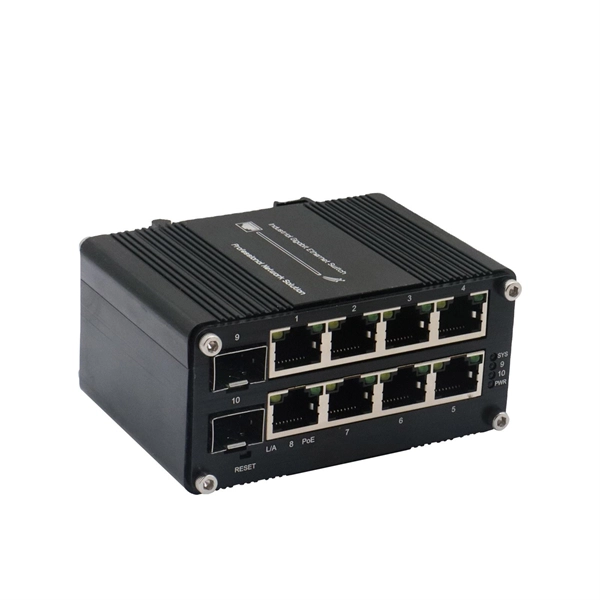
Insert a compatible SFP transceiver into the converter's port, making sure it matches the network's media type and speed. Then, connect one end of the fiber cable to the transceiver and the other to the appropriate port on a switch, router, or another media converter. Fiber media converters translate copper's electrical signals into fiber's optical signals, and back again. This allows networks to extend beyond the 100 m copper limit while gaining higher bandwidth and resistance to electromagnetic interference. In the illustrated setup, each LAN links to a. A fiber media converter is a networking device that allows you to convert a signal from one medium to another. This allows you to connect devices that use different types of cabling, such as a computer. While fiber optic ports are becoming increasingly common on networked electronics, the majority of connected devices still rely on RJ45 twisted pair connections. To help bridge the copper-fiber divide, media converters and transceiver modules (also known as SFPs or mini-GBICs) are often required. Use Fiber Media Converter in Your Network Media converters today are widely deployed in all. It is a device used to convert fiber optic cables to Ethernet cables to provide better connectivity. It is necessary to convert fiber optic signals to Ethernet signals because many network devices can only communicate with Ethernet signals. Fiber optic cables are known for the unmatched speed.
[PDF]
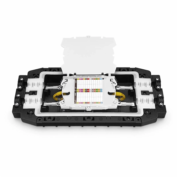
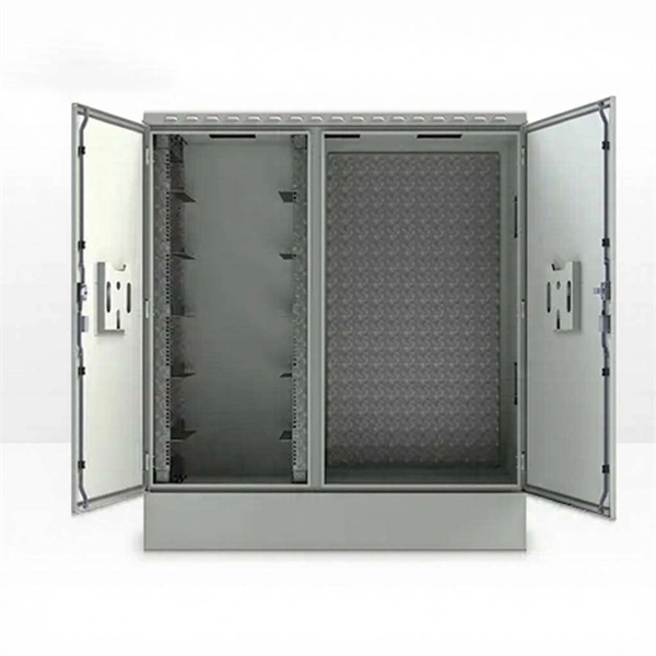
In this video, we take you through the step-by-step installation of Optical Distribution Frames (ODF) and Optical Fiber Patch Panels—key components in setting up a robust fiber optic network. At Eman Communications, we specialize in delivering high-quality installations that ensure opt. more In. Fiber optic patch panels are mostly mounted in 19 inch relay racks, but they can also be mounted on freestanding rails, in cabinets and also on walls. The fiber optical patch panel is convenient for people to easily access the optical fiber cable in the panel. Keeping this page as a placeholder for now. Have any questions? Talk with us directly using LiveChat. An ODF is a centralized platform designed for terminating, cross-connecting, and managing optical fibers. It ensures fiber management is structured, minimizes signal loss, and provides accessibility for maintenance and future expansion. ODF Rack/Cabinet: Physical frame housing all terminations and. To connect fiber optic cables to a patch panel, users must follow a specific procedure that ensures proper connectivity and signal transmission. Here is a step-by-step guide on how to connect fiber optic cables to a patch panel. Step 1: Gather the Tools and Equipment The first step in connecting.
[PDF]
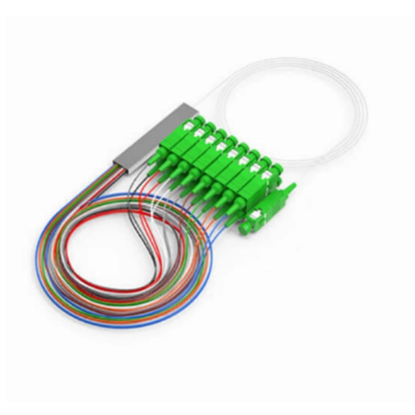
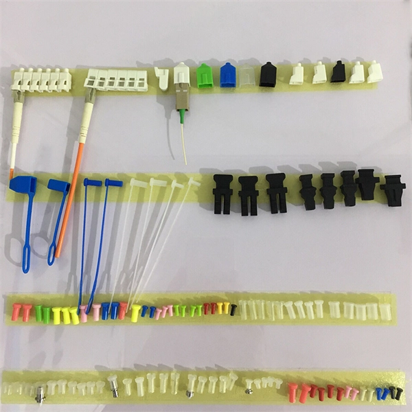
This interactive tutorial explores transmission and reflection of a light beam by three common beamsplitter designs. In addition to the task of dividing light, beamsplitters can be employed to recombine two separate light beams or images into a single path. The tutorial initializes with a cube. The fiber jumper connects the network devices at both ends and is used in the following three scenarios. FC Connector: use a metal sleeve for external reinforcement, fastened with a screw fastener. Generally used in the ODF (the most used on MDF) SC Connector: connected to the GBIC module, its. As title. It is a crucial part of many optical experimental and measurement systems, such as interferometers, also finding widespread application in fibre optic telecommunications. In its. The beam splitter has played numerous roles in many aspects of optics. For example, in quantum information the beam splitter plays essential roles in teleportation, bell measure-ments, entanglement and in fundamental studies of the photon. Electric elds E1 and E2 enter input ports 1 and 2. A beam splitter is an optical device that splits beams (such as laser beams) into two (or more) beams. Beam splitters typically come in the form of a reflective device that can split beams into exactly 50/50, half of the beam being transmitted through the splitter and half being reflected.
[PDF]
The input beam is spatially separated into two orthogonally polarized beams, diverging at an angle determined by the prism geometry and the material's properties. Beamsplitters are fundamental components in optical engineering, serving to precisely divide a single input beam of light into two distinct output beams. This division allows for the simultaneous analysis or utilization of the light's properties along two separate paths. It is a crucial part of many optical experimental and measurement systems, such as interferometers, also finding widespread application in fibre optic telecommunications. Additionally, beamsplitters can be used in reverse to combine two different beams into a single one. Polarizing beam splitters selectively transmit or reflect light depending on their polarization state, making them essential in a variety of optical applications.
[PDF]
You can test a photocoupler with a multimeter. This checks if its output changes when you power its input. This gives you the most accurate test results. This detailed guide will walk you through the process of testing an optocoupler using a multimeter, covering various scenarios and providing practical advice to ensure accurate results and avoid common pitfalls. We'll explore the underlying principles, delve into different testing methods, and. In this episode #0018 of Electronic Components Testing, we reveal how to test an optocoupler (optoisolator) using a digital multimeter step by step. This simple yet powerful technique will help you detect faulty optocouplers on circuit boards without desoldering them. Always. What are the methods to test optocoupler? The quality of the optocoupler can be determined by measuring the forward and reverse resistance of its internal diode and triode. Jotrin Electronics Limited will tell you that the reliable detection methods,as follows: 1. From basic circuit design to complex industrial systems, accurate optocoupler. Optocoupler is one type of ICs, It isolates input and output section by using optical technology this feature increase safety of circuit. Optocoupler has many part number, different part number has different output type so before checking it has to use part number to research with datasheet and.
[PDF]
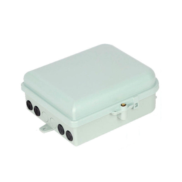
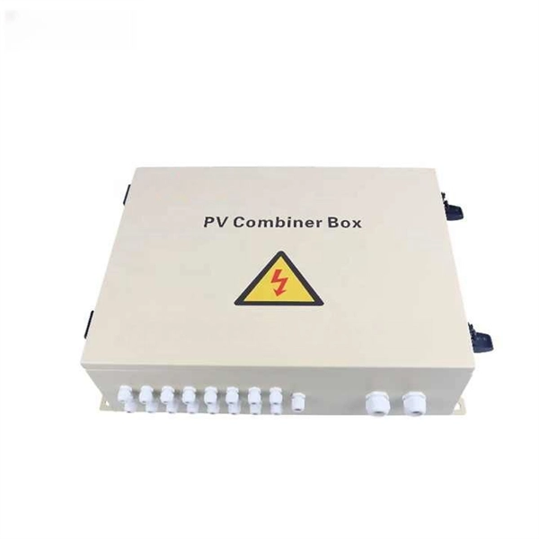
Here are some top ways to seal and waterproof your db box: Use waterproof sealants like silicone, polyurethane, or butyl rubber around doors and seams. Protect cables and connections with waterproof fittings and seals. Schedule regular maintenance and inspections to check for leaks. It is essential to use correct installation techniques to keep your outdoor electrical box waterproof. Follow these five steps for a secure install: Pick the right spot. Ensure children and pets can't reach it. Use a waterproof electrical box that meets industry standards. But in the real world, it also faces sun, heat, cold, vibration, and bad installation habits. I often tell clients that an outdoor box is like a rain jacket. For outdoor outlets, use a gfci outdoor outlet with. Regular care keeps your outdoor power distribution box functioning properly and your home safe in bad weather. Check your outdoor power box often for water damage. Finding problems early saves money and keeps it safe. Clearing trash prevents rust and. This article aims to provide a comprehensive guide on how to effectively cover an outdoor electrical box. The information presented covers the importance of weatherproofing, the selection of appropriate covers, the steps involved in installation, and essential safety precautions. Let's take a closer look at NEMA ratings and other weatherproofing considerations for.
[PDF]
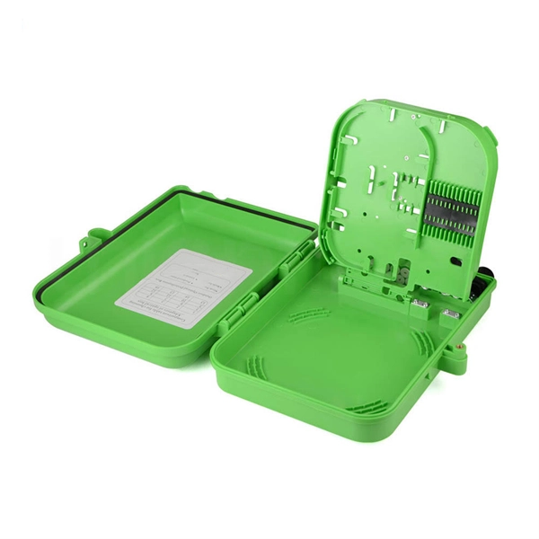
This video shows real on-site footage of electrical installation, demonstrating safe and standardized wiring methods used by professionals. Covers wiring, placement, standards, and expert tips for a compliant setup. A distribution box is the heart of any electrical system. It takes the incoming power and safely distributes it to different circuits throughout your building. It has three categories: residential, commercial and industrial electrical distribution boxes, all of which play important roles in their respective electrical. Box installation: Make sure that Distribution box has been correctly installed and fixed. Material preparation: Prepare the required circuit breakers, wires, wiring ties and other materials, and ensure that they meet the design drawings and installation requirements. Location determination:. In modern electrical systems, cable distribution boxes (also known as electrical distribution boxes or distribution boxes) play a crucial role as the key hub for managing, distributing, and protecting circuits. A 4 terminal junction box, also known as a 4-way junction box, is commonly used when there is a need to connect multiple wires or circuits together.
[PDF]
The country has already laid over 4,000 kilometers of fiber optic cables, covering major urban centers and key border crossings. However, the goal is to expand the network to a total of 7,000 kilometers, ensuring nationwide connectivity. The Afghanistan Telecommunications Regulatory Authority. Afghanistan is fast developing into a major trade and transit hub for subsea and transcontinental communication. Once completed, the 4,600 Afghan Fiber Optic Ring (also known as the Afghan National Civil Optical Fiber Cable-OFC ring network) within the broader regional “Digital Silk Road” aims to. Some experts believe fiber optics could serve as a key infrastructure for the growth of Afghanistan's digital economy. Sources have confirmed to TOLOnews that fiber optic internet services have been cut off in Nangarhar province, following earlier shutdowns in Kunduz, Baghlan, Takhar, Badakhshan. GL FIBER & High-Performance Fiber Optic Network Deployment in. Scope: Deployment of a 1,200-km fiber optic backbone network integrating aerial, underground, and submarine routes to enhance national broadband connectivity and support 5G/FTTH rollout. Enayatullah Alokozay, the spokesperson for the ministry, stated that the operations to extend and connect the fiber optic network have.
[PDF]
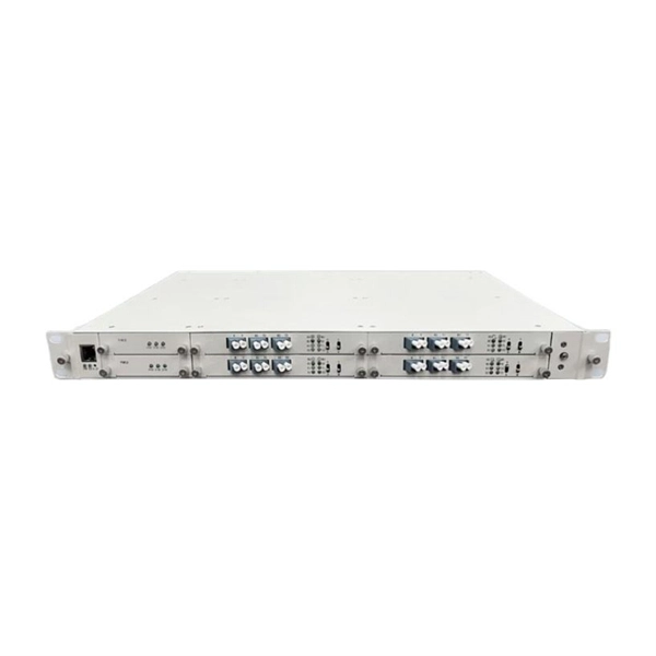
This article provides a detailed exploration of Fiber Amplifiers—what they are with regards to Fiber Cabling, how they function, their types, and their significance. Probably the most important application of fiber amplifiers is in optical fiber communications, i., data transmission through optical fibers., every 50 km of fiber. Based on their location and function within the fiber optic line, they are generally categorized as relay amplifiers, preamplifiers, and power amplif. more How to use a fiber. This article explains what optical amplifiers are, how optical amplifiers work, their main types, and why optical amplifiers are indispensable in modern fiber networks. What Is an Optical Amplifier? An optical amplifier is a device that increases the intensity of a light signal traveling through an. High Power Fiber Amplifiers (HPFAs) are critical components in modern optical systems, designed to boost weak optical signals into high-power outputs. Whether you're building long-distance communication links or powering high-intensity laser applications, HPFAs offer the performance, stability, and. Amplification can take place in two ways: the optical signal can be detected, converted to an electrical signal, then returned to the optical domain by modulating an optical source, or an amplifier that directly amplifies the optical signal can be used. The fiber is doped with rare earth elements, such as.
[PDF]
This guide provides cost estimates in USD with low, average, and high ranges and explains what drives these prices. Assumptions: region, service call for electrical work, permit requirements, and box type vary by locality. The total project range typically falls between $1,500. How much does it cost to replace an outside electrical meter box? Get free estimates for your project or view our cost guide below: Electric meter box replacement costs $500 to $2,100 on average, depending on the meter size, location, installation complexity, and code requirements. New outside. Homeowners typically pay a lump-sum for electric meter installation ranging from modest upgrades to full service upgrades. The main drivers are meter type, service size, local permitting, and whether utility work is required. The price range below reflects common U. scenarios and includes both. Replacing a home meter box typically costs between US $500–$2,100, though large or complex jobs — like 400-amp or full service upgrades — may reach $5,000+, depending on wiring, permits, and labor. Professional installation ensures NEC compliance, proper grounding and bonding, and successful inspection approval. Cost ranges reflect total project price plus typical per-unit components.
[PDF]
Use this worksheet to input values for all variables that will impact your system's performance. After entering your values, please ensure you click the 'Calculate Link Loss' button at the bottom of the page to generate your total link loss. Add connectors, splices, bends, and safety margin easily. See results instantly above the form, then adjust values. Choose a mode, then enter values and optional losses. All calculations use base-10 logarithms. mW must be greater than zero. Used only in measured attenuation mode. Length is needed. The power budget refers to the amount of fiber optic cable plant loss that a datalink (transmitter to receiver) can tolerate in order to operate properly. Sometimes the power budget has both a minimum and maximum value, which means it needs at least a minimum value of loss so that it does not. To detect whether the link runs properly, the following calculation should be performed. It is often the case to calculate the maximum signal loss across a given fiber link during optical cable installation. First, you should be aware of the fiber loss formula: The Total Link Loss = Cable. Therefore, it is very important to calculate the fiber loss and take appropriate steps. In order to get the most reliable results, an Optical Time Domain Reflectometer (OTDR) trace of the actual fiber connection should be completed. This will provide you with the real.
[PDF]
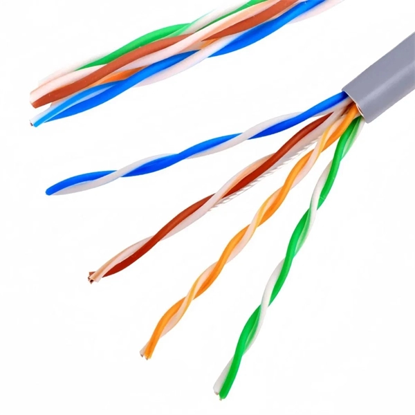
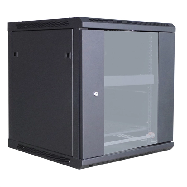
Rack Elevation or Server Rack Layout Software are simple tools to plan and document the cabling of your server cabinet. To make it even easier for you, we launched the free online Rack Planner. It helps you create a helpful rack diagram and keep your network tidy. Network cabinet cabling describes the structured connection and arrangement of all IT components in a server rack. The aim is a secure, maintainable and scalable operation of the network environment. Step-by-step guide: In this way, patch panels, switches, cable routing and documentation are. Creating a rack diagram is an important step to having sustainable good cable management in the network cabinet. Let's take a look at the essential components, selection criteria, and best practices for efficiency, order and protection of the network. Use cabinet screws to fix the network patch panel to the network cabinet. Note the wiring sequence on the patch panel when wiring, as T568A and T568B have different sequences. Wiring a server or network rack feels simple at first. Cables plug in, and devices turn on. Then problems appear. Slow speeds and tangled wires with card troubleshooting. Clean wiring prevents those issues before they start.
[PDF]