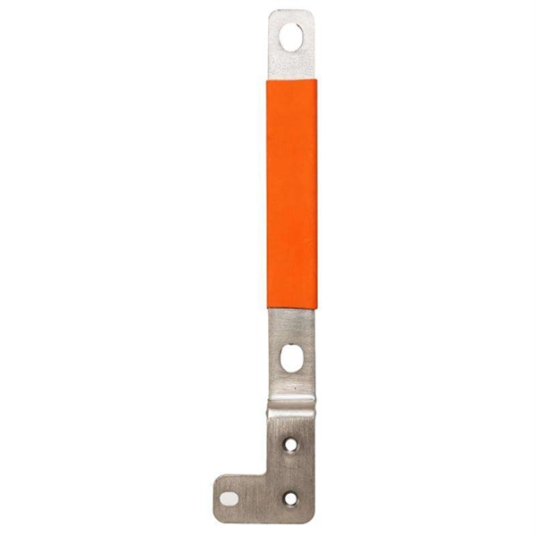
On the US market, a 5. 26 mm 2 (10 AWG) ground wire must be used, and in all other markets a 6 mm 2 must be used. Grounding of the units: Attach a ground wire from one of the threaded studs (A) at the bottom of the housing, to the mounting plate (B). Attach a second grounding wire from the mounting. The correct connection method of Distribution box grounding wire mainly includes the following steps: 1. Find the grounding bar or PE bar Open the distribution box and find the position marked with the grounding plate or PE letter. The basic rule achieves this through an equipment grounding jumper; four exceptions. An equipment grounding conductor passing through the box without a splice is not required to be joined inside the box to others that are spliced in the box. 148 addresses the continuity of equipment grounding conductors and their attachment in boxes. Not all boxes are metal or provide. Correct grounding of services depends upon understanding the definition and role of the grounded conductor. The neutral conductor is typically the grounded conductor connected to the system's neutral point, carrying current under normal operation. Whether you're a seasoned pro or just starting out, this comprehensive guide will give you practical.
[PDF]
Each wire must connect to its appropriate terminal: Live wires (red or brown) connect to the MCB's live terminal. Neutral wires (black or blue) go to the neutral bus bar. Welcome to our channel! In this video, we'll walk you through the process of wiring a home distribution box with a detailed connection diagram. Whether you're an electrician or a DIY enthusiast, this guide will. This guide provides step-by-step instructions for connecting a distribution box and highlights key factors to consider during installation. What Is a Distribution Box? A distribution box, also known as an electrical distribution board, is a critical component in electrical systems. In Single Phase supply (230V in UK, EU and 120V & 240V in the US & Canada), there are two (one is Line (aka Phase, Hot or Live) and the other one is Neutral) incoming cables from the utility poles to the kWh energy. A distribution board or distribution box is where the main power supply is distributed to multiple loads. And all the switching and protective devices are installed in the distribution box. Single Phase Distribution Box generally consists of Double Pole MCBs, Single Pole MCBs, and RCCBs.
[PDF]
This video goes over common types of connectors, their respective adapters, and how to properly connect and disconnect them. For your safety, it is always advised to follow proper fiber optic handling techniques and utilize the correct protective gear when performing. Fiber optic adapters, also known as couplers, play a crucial role in fiber optic networks by providing a connection point between two fiber optic connectors. They enable seamless and reliable optical signal transmission between different fiber optic cables, connectors, or devices. In this tutorial. Proper connection of fiber optic cables is essential to harness these benefits fully, as even minor errors can lead to significant performance issues like signal loss. more Are you interested in seeing how fiber optic connectors get. Vigitron's Vi5004 is a 4-port fiber optic media convertor that enables Ethernet signals to be transmitted over fiber optic cables. It enable UTP Ethernet to connect to fiber to meet long distance transmission requirement or where fiber is already installed. Why Use Fiber Optic Internet? Before diving into the setup, let's quickly recap why fiber optics are worth the effort: Lightning-fast speeds (up to 1 Gbps or higher). Low latency for.
[PDF]
This video shows real on-site footage of electrical installation, demonstrating safe and standardized wiring methods used by professionals. more Learn how to wire a distribution box step by step! This video shows real on-site footage of. Hey, in this article we are going to see the Single Phase Distribution Box Wiring Diagram and Connection Procedure. A distribution board or distribution box is where the main power supply is distributed to multiple loads. And all the switching and protective devices are installed in the. Box installation: Make sure that Distribution box has been correctly installed and fixed. Material preparation: Prepare the required circuit breakers, wires, wiring ties and other materials, and ensure that they meet the design drawings and installation requirements. Location determination:. In this video, we'll walk you through the process of wiring a home distribution box with a detailed connection diagram. Whether you're an electrician or a DIY enthusiast, this guide will help you understand the basics of home electrical distribution. What Is a Distribution Box? A distribution box, also known as an electrical distribution board, is a critical component in electrical systems. It serves as a.
[PDF]
In this video, we'll walk you through the process of wiring a home distribution box with a detailed connection diagram. Whether you're an electrician or a DIY enthusiast, this guide will help you understand the basics of home electrical distribution. more Welcome to our channel! In this video. A distribution board or distribution box is where the main power supply is distributed to multiple loads. And all the switching and protective devices are installed in the distribution box. Single Phase Distribution Box generally consists of Double Pole MCBs, Single Pole MCBs, and RCCBs. Single Phase wiring installation is the most common wiring in residential buildings. It is essential for managing the electrical supply to various appliances and circuits in the building. Its function is to safely divide the incoming high-amperage utility power into smaller, manageable branch circuits that supply power to lights, outlets, and.
[PDF]
In this video, we'll walk you through the process of wiring a home distribution box with a detailed connection diagram. Whether you're an electrician or a DIY enthusiast, this guide will help you understand the basics of home electrical distribution. more Welcome to our channel! In this video. A distribution box is the heart of any electrical system. It takes the incoming power and safely distributes it to different circuits throughout your building. However, the key to. In this article, we'll explain how to install a weatherproof electrical box, from selecting the right materials to properly securing the box in place. Weatherproof electrical boxes are designed to handle extreme weather conditions, such as heavy rain and strong winds. They're also designed to. Whether you're a do-it-yourselfer, the neighborhood handyman, or a professional electrician, knowing how to properly install a weatherproof electrical junction box can save time, and your system components will continueto operate for years. Standard indoor electrical boxes are not designed to handle exposure to rain, snow, or high humidity, which can quickly lead to corrosion. Whether adding a GFCI outlet for safety or upgrading an exterior outlet for weather-resistant durability, it's essential to follow proper electrical wiring guidelines to ensure compliance with local codes and prevent hazards. This guide explains the different types of outdoor electrical boxes.
[PDF]
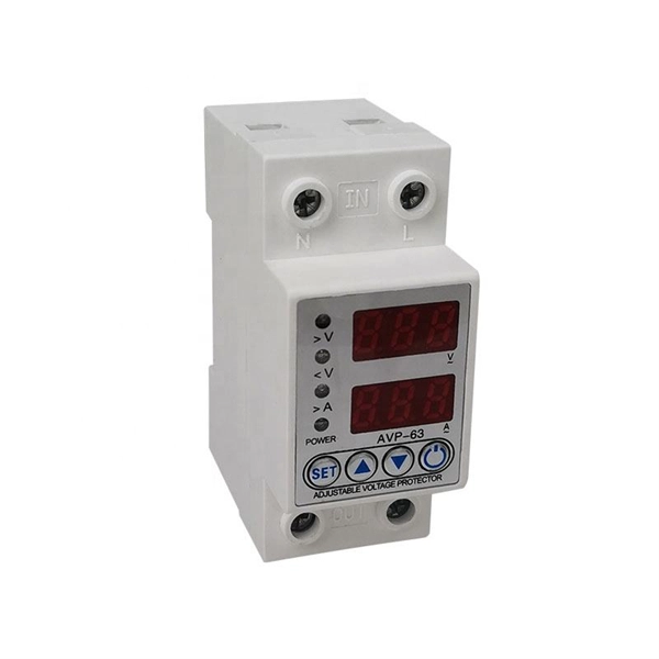
Practice good wiring: secure grounding, neat cable management, proper insulation, and correct wire gauge and breaker size. Include protection devices like breakers, fuses, and surge protectors—each circuit should have its own protection. Comply with standards: Follow NEC, IEC . We'll show you how to run the wires, install the proper jacks and hook up the central distribution box. The new system doesn't mean you have to scrap your old cables and jacks. Existing phone lines and jacks can coexist with your new communication wiring system. We recommend that you initially. Learn how to wire a distribution box step by step! This video shows real on-site footage of electrical installation, demonstrating safe and standardized wiring methods used by professionals. And all the switching and protective devices are installed in the distribution box. Single Phase Distribution Box generally consists of Double Pole MCBs, Single Pole MCBs, and RCCBs. It is usually equipped with circuit breakers, fuses, terminal connectors, and other components. It is mainly used to isolate fault circuits, prevent overload, and ensure the safe operation of. Material preparation: Prepare the required circuit breakers, wires, wiring ties and other materials, and ensure that they meet the design drawings and installation requirements. Location determination: Determine the installation position of the circuit breaker according to the position of the.
[PDF]
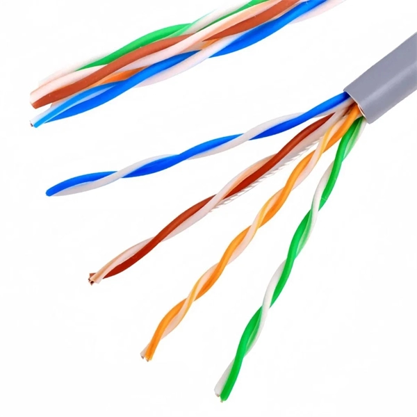
This guide will provide you with a detailed Cat 6 socket wiring diagram, outlining the necessary steps and components required for a successful installation. If you want to install a classic network socket, you must first strip the Cat. A special stripping tool for data cables is used here – for example, the Stripper No. Use side A to remove the protective jacket. 35, you can shorten the network cable (Cat. 7) a little bit, if required. If you have too much cable left, it will be harder to. Learn how to wire a distribution box step by step! This video shows real on-site footage of electrical installation, demonstrating safe and standardized wiring methods used by professionals. 5mm² wires, and the air conditioning circuit can use 2. Connection method: Each switch takes a wire from the incoming point and connects it to the incoming end of the switch, or uses parallel connection to reduce the difficulty. Learn how to install a distribution box safely and correctly. Covers wiring, placement, standards, and expert tips for a compliant setup. A distribution box is the heart of any electrical system. It takes the incoming power and safely distributes it to different circuits throughout your building. Understanding the wiring diagram of an electrical panel box is essential for electricians and homeowners alike, as it allows them to troubleshoot any electrical issues, carry out repairs, or make additions to the system.
[PDF]
This article provides a detailed exploration of Fiber Amplifiers—what they are with regards to Fiber Cabling, how they function, their types, and their significance. Probably the most important application of fiber amplifiers is in optical fiber communications, i., data transmission through optical fibers., every 50 km of fiber. Based on their location and function within the fiber optic line, they are generally categorized as relay amplifiers, preamplifiers, and power amplif. more How to use a fiber. This article explains what optical amplifiers are, how optical amplifiers work, their main types, and why optical amplifiers are indispensable in modern fiber networks. What Is an Optical Amplifier? An optical amplifier is a device that increases the intensity of a light signal traveling through an. High Power Fiber Amplifiers (HPFAs) are critical components in modern optical systems, designed to boost weak optical signals into high-power outputs. Whether you're building long-distance communication links or powering high-intensity laser applications, HPFAs offer the performance, stability, and. Amplification can take place in two ways: the optical signal can be detected, converted to an electrical signal, then returned to the optical domain by modulating an optical source, or an amplifier that directly amplifies the optical signal can be used. The fiber is doped with rare earth elements, such as.
[PDF]
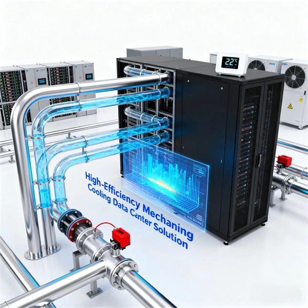
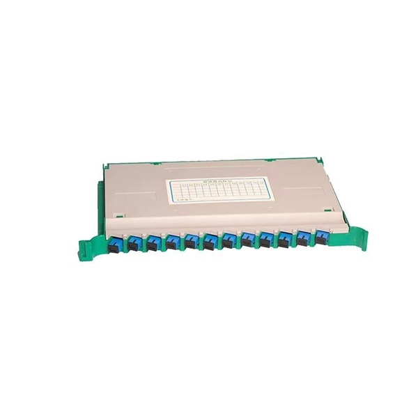
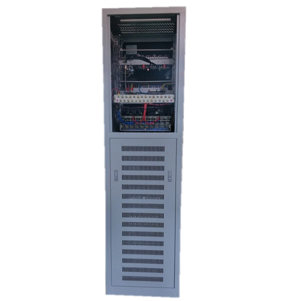
Rack Elevation or Server Rack Layout Software are simple tools to plan and document the cabling of your server cabinet. To make it even easier for you, we launched the free online Rack Planner. It helps you create a helpful rack diagram and keep your network tidy. Network cabinet cabling describes the structured connection and arrangement of all IT components in a server rack. The aim is a secure, maintainable and scalable operation of the network environment. Step-by-step guide: In this way, patch panels, switches, cable routing and documentation are. Creating a rack diagram is an important step to having sustainable good cable management in the network cabinet. Let's take a look at the essential components, selection criteria, and best practices for efficiency, order and protection of the network. Use cabinet screws to fix the network patch panel to the network cabinet. Note the wiring sequence on the patch panel when wiring, as T568A and T568B have different sequences. Wiring a server or network rack feels simple at first. Cables plug in, and devices turn on. Then problems appear. Slow speeds and tangled wires with card troubleshooting. Clean wiring prevents those issues before they start.
[PDF]
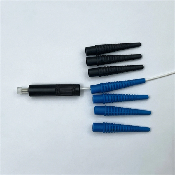
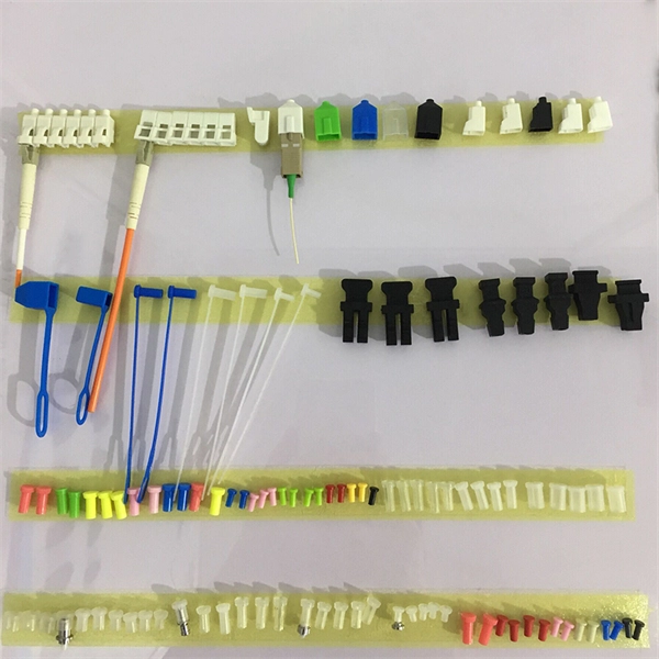
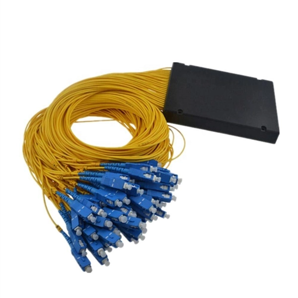
Fiber optic pigtails have only one terminated connector on one side but bare fibers on another side. Executive Summary: A fiber optic pigtail is one of the most commonly specified yet least understood components in structured cabling. Get the wrong connector type, the wrong polish, or skip proper fusion splicing technique—and you're looking at elevated signal loss, increased back reflection, and a. When you build or upgrade a fiber network, the same four words pop up everywhere— fiber optic (bare fiber), pigtail, patch cord, optical cable. They're related, but they are not interchangeable. Mixing them up drives costs higher, increases loss, and slows your rollout. The good news? Once you nail. A fiber pigtail is typically a fiber optic cable with one end factory pre-terminated fiber connector and the other exposed fiber. It is usually suitable for field termination using a mechanical or fusion splicer. It primarily finds its application in terminating optical fibers on networking equipment, including patch panels, distribution frames, or optical transceivers. The bare end is normally.
[PDF]
A 4-core fiber optic cable is a type of cable that contains four individual optical fibers within a single protective jacket. These fibers are used to transmit data as light signals, offering high-speed data transfer capabilities over long distances with minimal loss. This guide covers everything you need to know about 4 core fiber, including its internal structure, TIA standard color coding, and how to choose the right type. They are used to connect final user to FTTH or GPON line. Jera is a direct manufacturer who supply a wide range product for. This cable can be used for LAN and WAN backbones, telecom access lines, fibre to business and fibre to the building or the homme connections. It is equally suited for installation in ducts and on trays. This cable features a 0. 15mm corrugated steel armour which makes it rodent proof. OM3 and higher. A TOSLINK optical fiber cable with a clear jacket. What is a 4 Core Optical Cable? A 4 Core Optical Cable is a fiber optic cable that contains four individual optical fibers within a single. Unlike copper wires, which are limited by lower data transmission speeds, shorter transmission distances, and higher susceptibility to electromagnetic interference, fiber optic cables offer unparalleled performance and can cover much greater distances without bumping up against signal degradation.
[PDF]
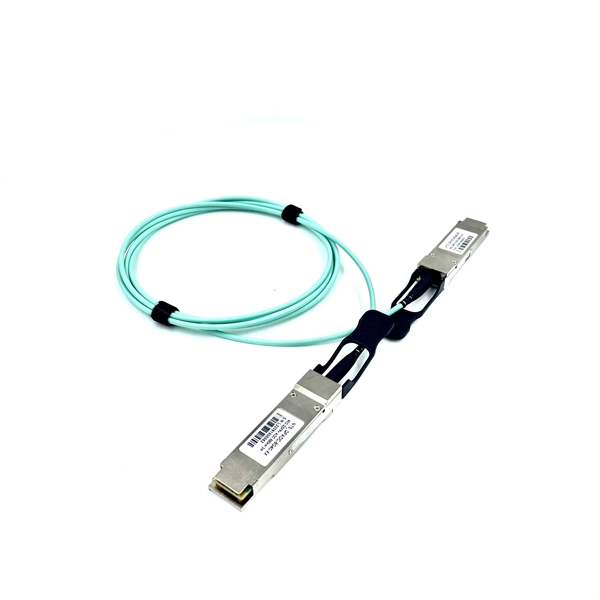
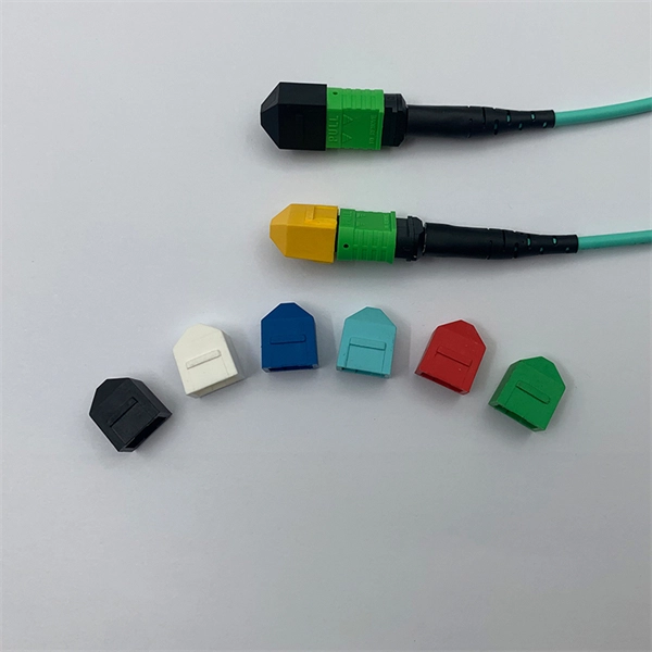
This step-by-step guide aims to provide a comprehensive understanding of the techniques and considerations involved in successfully connecting optical fibers, offering invaluable insights for professionals and enthusiasts in the field. In high-speed data networks, the seamless integration of fiber optic cables with SFP (Small Form-Factor Pluggable) modules is critical for reliable signal transmission. SFP transceivers bridge electrical and optical signals, making them indispensable in data centers, telecom networks, and. Proper connection of fiber optic cables is essential to harness these benefits fully, as even minor errors can lead to significant performance issues like signal loss. This article will guide you through the necessary tools, materials, and methods on how to connect fiber optic cables effectively. This section describes how to install optical transceivers on the SFP or SFP+ ports and connect them to the ports of the peer device using optical fibers according to the network plan. The USG supports both 1 Gbit/s, 10 Gbit/s, and 40 Gbit/s optical modules. The optical modules at both ends are. There are many types of fiber optic connectors, including SC, LC, FC, ST, D4, MU, MT/MPO, etc. These connectors can be divided into single-mode and multi-mode fiber optic connectors according to their structure and purpose. In this tutorial.
[PDF]
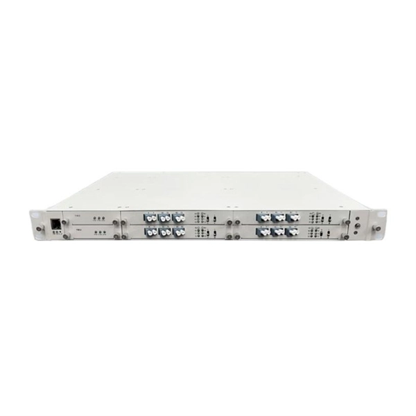
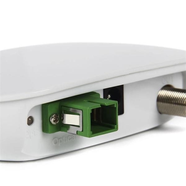
Insert a compatible SFP transceiver into the converter's port, making sure it matches the network's media type and speed. Then, connect one end of the fiber cable to the transceiver and the other to the appropriate port on a switch, router, or another media converter. Fiber media converters translate copper's electrical signals into fiber's optical signals, and back again. This allows networks to extend beyond the 100 m copper limit while gaining higher bandwidth and resistance to electromagnetic interference. In the illustrated setup, each LAN links to a. A fiber media converter is a networking device that allows you to convert a signal from one medium to another. This allows you to connect devices that use different types of cabling, such as a computer. While fiber optic ports are becoming increasingly common on networked electronics, the majority of connected devices still rely on RJ45 twisted pair connections. To help bridge the copper-fiber divide, media converters and transceiver modules (also known as SFPs or mini-GBICs) are often required. Use Fiber Media Converter in Your Network Media converters today are widely deployed in all. It is a device used to convert fiber optic cables to Ethernet cables to provide better connectivity. It is necessary to convert fiber optic signals to Ethernet signals because many network devices can only communicate with Ethernet signals. Fiber optic cables are known for the unmatched speed.
[PDF]
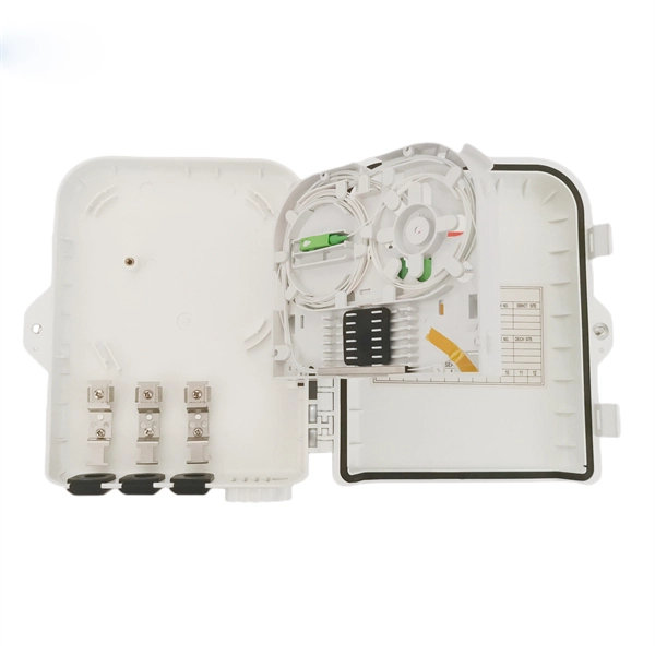
It receives power from the main electrical supply and divides it into separate circuits, each protected by circuit breakers or fuses. The primary purpose of a distribution box is to provide a safe and organized way to control electrical circuits. In this guide, we'll break down the 12 main types of distribution boxes in a way that's easy to understand. We'll chat about what each one does, where it shines, and then dive into how to choose the perfect box for your needs. Plus, we'll sprinkle in some practical tips to make sure you're not. A distribution box, also known as a power distribution box or electrical distribution box, is used to distribute electrical power safely to multiple circuits. It helps organize, protect, and control electrical connections in residential, commercial, and industrial electrical systems. It acts like a hub or traffic controller, managing power flow to different areas or devices. What is the distribution box? A. Electrical systems power our homes, offices, and industrial facilities, but behind every reliable electrical setup lies a crucial component that often goes unnoticed: the distribution box. This essential piece of equipment serves as the nerve center of your electrical system, managing power flow.
[PDF]