Check the electrical load and ensure that the sensors do not exceed the 10 Amp maximum. Check each wire for damage that may lead to a short. Check the tightness of electrical connections along the power. Understanding how to safely and effectively test a breaker box with a multimeter is a crucial skill for any homeowner or electrician. Regular testing can help identify potential problems, prevent electrical hazards, and ensure the reliable operation of your electrical system. Ignoring this vital. When devices in your new box don't work, you start by testing the circuit. You will want a voltage tester (doesn't need to be a voltmeter) for this job. The very cheapest one you can find at a local hardware store (or online) will work great. In the merger we can see a red wire and a black wire connect the red wire to the megger's line terminal and then. This article summarizes inspection of the building electrical panel, main panel, or electrical distribution and sub panels. A continuity tester is the simplest tool for the specific task of checking for continuity.
[PDF]
A common test setup to evaluate Stressed Receiver Sensitivity involves measuring the Optical Modulation Amplitude (OMA) using a square wave, per the standard guidelines. Receiver sensitivity stands as a critical parameter impacting an optical transceiver's functionality. It denotes a module's capability to function in challenging environments and aids network operators in determining the system's maximum reach or link margin. These metrics provide insights into how well your transceivers perform under different conditions, ensuring seamless data transmission. Optical. Whether you're a network engineer validating new inventory or an integrator preparing for deployment, knowing how to test optical transceiver modules can save time, reduce failures, and ensure SLA compliance. Unchecked optical modules can cause: Testing ensures compliance with IEEE 802. 3 and MSA. In optical communication systems, sensitivity is a measure of how weak an input signal can get before the bit-error ratio (BER) exceeds some specified number. The standards body governing the application sets this specified BER. For example, SONET specifies that the BER must be 10 -10 or better. Why Fiber Optic Transceiver Testing is Important? Identify faults and failures: Transceiver testing helps in identifying any faults.
[PDF]
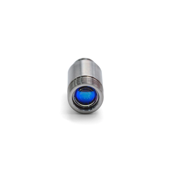
A spectrophotometer is a piece of spectroscopy equipment measures the amount of light absorbed by a sample. This measurement can be useful in many research applications: To identify materials by mapping molecular absorption profiles. To work out solute concentrations in solutions. Specifically, a UV-Visible Spectrometer measures the absorption or transmission of light in the ultraviolet (UV) and visible (Vis) regions of the electromagnetic. A spectrometer is a scientific instrument that analyzes light to reveal information about materials. It functions by separating light into its constituent wavelengths, much like a prism splits sunlight into a rainbow. This analytical capability makes spectrometers valuable tools across many fields. Spectrophotometry is an experimental technique that is used to measure the concentration of solutes in a specific solution by calculating the amount of light absorbed by those solutes. It is widely used in laboratories to analyze various substances, from liquids to gases. Here's a step-by-step guide on how to use a spectrophotometer. When you use spectrophotometry, you gain skills that help in many science fields. This guide makes spectroscopy simple by showing you how to use teaching tools and real experiments. The basic principle is that each compound absorbs or transmits light over a certain range of wavelength. This measurement can.
[PDF]
What is the cost of a relay coordination study in Singapore ? The cost of a protective device study in Singapore depends on the complexity of the electrical system, facility size, and number of relays. I2R, as a firm of Professional Engineers and Licensed Electrical Workers, is qualified under the Electricity Act to carry out all types of electrical testing and commissioning works to ensure that electrical apparatus are fit for power energization and safe for use and operation. We have all the. We are Specialized in Low Voltage Switchgears Testing, Commissioning, Maintenance and Installations from OEM's. We do factory Acceptance and Site Acceptance Testing and Commissioning support of LV Switchgears. Earth loop impedance measurments. Care Offers cost-effective solutions for protective device coordination in compliance with. Advance Engineering and Testing (AET) Pte Ltd established on 2019, is a top provider of electrical testing ranging from commercial, domestic, and industrial. The company provides 24/7 onsite support with prioritization of customer satisfaction. Their vision and mission statement is to continuously. The type of testing required for each specific relay needs to be designed with the goal of accomplishing the objective. We perform testing in four specific classes which. Our services are applicable to a number of industries such as Petrochemical industries, Oil and gas fabrication industries, Wafer fabrication plants, Pharmaceuticals.
[PDF]
To check a fiber connection, connect a jumper to the optical source port and the other end to an optical meter. Press the “test” or “signal” button to send a signal from the source to the meter. In this blog, we'll explore different methods, including using a flashlight, advanced tools like Fluke testers, and more cost-effective options for testing fiber optics. First, we'll show you the. This guide will walk you through diagnosing and resolving common fiber network issues efficiently. Why Do Fiber Networks Fail? Despite their robustness, fiber networks can fail due to: Physical Damage : Cuts, bends, or contamination in fiber cables or connectors. Below is an in-depth guide on how to assess the health and performance of a fiber optic connection: Before relying on technical tools, start. While there are many different fiber optic cable tests, the most common version is an insertion loss test, also known as an attenuation, jumper, or connectivity test. This test requires a special testing kit and protective eyewear, but it will help you diagnose problems with the cable's. We'll explain why it's vital to test fiber optic cables, the three most popular methods, and when you should use them. Related: Fiber Optic Connectors – Identification Guide Regularly testing fiber optic cables helps minimize network downtime, lengthens the network's longevity, reduces maintenance.
[PDF]
You can test a photocoupler with a multimeter. This checks if its output changes when you power its input. This gives you the most accurate test results. This detailed guide will walk you through the process of testing an optocoupler using a multimeter, covering various scenarios and providing practical advice to ensure accurate results and avoid common pitfalls. We'll explore the underlying principles, delve into different testing methods, and. In this episode #0018 of Electronic Components Testing, we reveal how to test an optocoupler (optoisolator) using a digital multimeter step by step. This simple yet powerful technique will help you detect faulty optocouplers on circuit boards without desoldering them. Always. What are the methods to test optocoupler? The quality of the optocoupler can be determined by measuring the forward and reverse resistance of its internal diode and triode. Jotrin Electronics Limited will tell you that the reliable detection methods,as follows: 1. From basic circuit design to complex industrial systems, accurate optocoupler. Optocoupler is one type of ICs, It isolates input and output section by using optical technology this feature increase safety of circuit. Optocoupler has many part number, different part number has different output type so before checking it has to use part number to research with datasheet and.
[PDF]
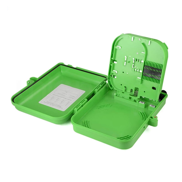
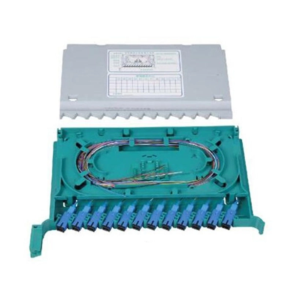
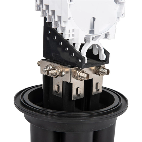
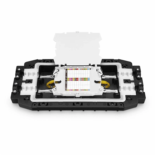
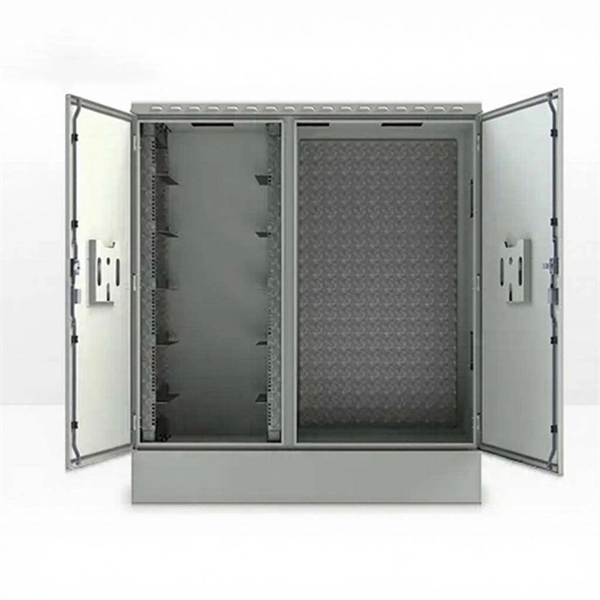
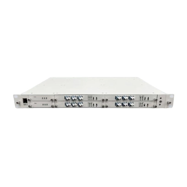
Learn how to install a fiber distribution cabinet step by step, including mounting, cable routing, grounding, and testing for FTTH networks. The installation of a fiber distribution cabinet involves five key steps: site selection, cabinet mounting, cable routing, fiber splicing, and grounding +. This step is very simple, we only need to install brackets on both sides of the optical fiber distribution box, and then fix the brackets to the designated position of the rack with screws. It should be noted that before installing the optical fiber distribution box, the installation direction of. Keeping this page as a placeholder for now. Have any questions? Talk with us directly using LiveChat. Read and understand this procedure (as well as the instructions provided with related assemblies) before beginning an installation. Do not discard this instruction; keep it on hand for future reference. Familiarize yourself to understand the unit's placement in your network. The 1U fiber optic distribution box is used as an example to introduce its structure. Three adapter panels can be installed on the front panel of this fiber optic distribution. Fiber Distribution Hub Installation Procedure - Optical Cable Corporation Products Fiber Copper Hybrid Cabinets, Racks, Enclosures Deployable Solutions Industries Oil & Gas Mining Industrial BroadcastAV Military Commercial Enterprise library & Support Contact Resources About OCC News Careers.
[PDF]
Calm the chaos by following clear current, temperature, and clearance rules from IEC 61439 guidelines and this handy overview from ABB's busbar selection guide: ABB Busbar Applications Handbook. In the power transmission and distribution system, busbar is the core conductive component, which is widely used in high-voltage transmission, data center, new energy, rail transportation, industrial automation and other fields. Different types of busbars have their own characteristics in terms of. Prices of bus bar assemblies vary depending upon quantity ordered. In addition, individual dimensional characteristics, materials, manufacturing techniques, the interconnection scheme, plating finish, insulation, and hardware requirements affect overall cost. Busbars act as the main current highways inside high voltage switchboards, linking incoming feeders. When designing electrical power systems, one of the most critical aspects is selecting the right size for busbars. Busbars are the backbone of switchboards, distribution boards, and electrical panels. The group of busbars are consisting of 5 bars, one for each phase, one for neutral and one. To connect various high voltage (HV) components to the HV system, TE also delivers a wide variety of busbars. In cooperation with the customer, these can also feature TE's Bus Bar Insulation Tubing (BBIT). Busbars provide a safe HV connection on shorter distances. Especially in the area near the.
[PDF]
This guide breaks down exactly what you are paying for, what a defensible 2026 FOB China price range actually looks like, and how to spot quotes that either undercut reality or overcharge for features you don't need. 💡 Need to vet the supplier behind the quote? Pair this with our PV combiner box. The global market for Photovoltaic DC Distribution Boxes was valued at USD 892. 65 Million in 2025, marking a period of sustained capital appreciation from its 2020 valuation of USD 520. This growth is propelled by increasing renewable energy investment, supportive government policies, and the declining cost of solar panels. A Photovoltaic Distribution Box, also known as a PV distribution box or solar combiner box, is an essential component in a photovoltaic (PV) system that helps manage the electrical connections and distribution of power generated by solar panels. It is usually installed at key locations in photovoltaic power plants to bring together DC power from multiple photovoltaic modules and distribute and control it through. The market for photovoltaic distribution boxes is dynamic and competitive. Selecting the right supplier is critical for system safety, efficiency, and long-term project viability. This guide examines current trends, selection criteria, and key suppliers for this essential B2B component.
[PDF]
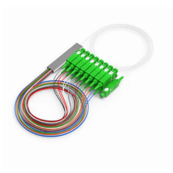
The input beam is spatially separated into two orthogonally polarized beams, diverging at an angle determined by the prism geometry and the material's properties. Beamsplitters are fundamental components in optical engineering, serving to precisely divide a single input beam of light into two distinct output beams. This division allows for the simultaneous analysis or utilization of the light's properties along two separate paths. It is a crucial part of many optical experimental and measurement systems, such as interferometers, also finding widespread application in fibre optic telecommunications. Additionally, beamsplitters can be used in reverse to combine two different beams into a single one. Polarizing beam splitters selectively transmit or reflect light depending on their polarization state, making them essential in a variety of optical applications.
[PDF]
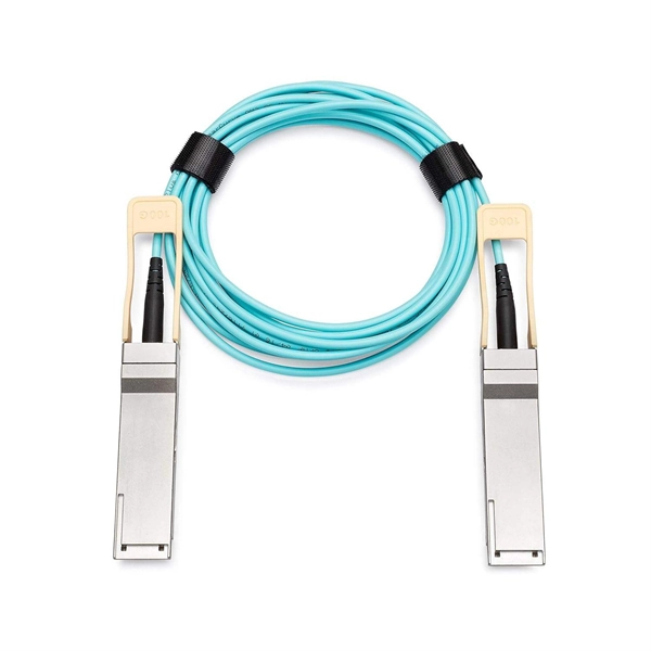
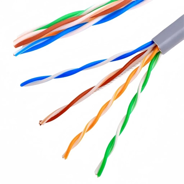
A 4-core fiber optic cable is a type of cable that contains four individual optical fibers within a single protective jacket. These fibers are used to transmit data as light signals, offering high-speed data transfer capabilities over long distances with minimal loss. This guide covers everything you need to know about 4 core fiber, including its internal structure, TIA standard color coding, and how to choose the right type. They are used to connect final user to FTTH or GPON line. Jera is a direct manufacturer who supply a wide range product for. This cable can be used for LAN and WAN backbones, telecom access lines, fibre to business and fibre to the building or the homme connections. It is equally suited for installation in ducts and on trays. This cable features a 0. 15mm corrugated steel armour which makes it rodent proof. OM3 and higher. A TOSLINK optical fiber cable with a clear jacket. What is a 4 Core Optical Cable? A 4 Core Optical Cable is a fiber optic cable that contains four individual optical fibers within a single. Unlike copper wires, which are limited by lower data transmission speeds, shorter transmission distances, and higher susceptibility to electromagnetic interference, fiber optic cables offer unparalleled performance and can cover much greater distances without bumping up against signal degradation.
[PDF]
This guide provides cost estimates in USD with low, average, and high ranges and explains what drives these prices. Assumptions: region, service call for electrical work, permit requirements, and box type vary by locality. The total project range typically falls between $1,500. How much does it cost to replace an outside electrical meter box? Get free estimates for your project or view our cost guide below: Electric meter box replacement costs $500 to $2,100 on average, depending on the meter size, location, installation complexity, and code requirements. New outside. Homeowners typically pay a lump-sum for electric meter installation ranging from modest upgrades to full service upgrades. The main drivers are meter type, service size, local permitting, and whether utility work is required. The price range below reflects common U. scenarios and includes both. Replacing a home meter box typically costs between US $500–$2,100, though large or complex jobs — like 400-amp or full service upgrades — may reach $5,000+, depending on wiring, permits, and labor. Professional installation ensures NEC compliance, proper grounding and bonding, and successful inspection approval. Cost ranges reflect total project price plus typical per-unit components.
[PDF]
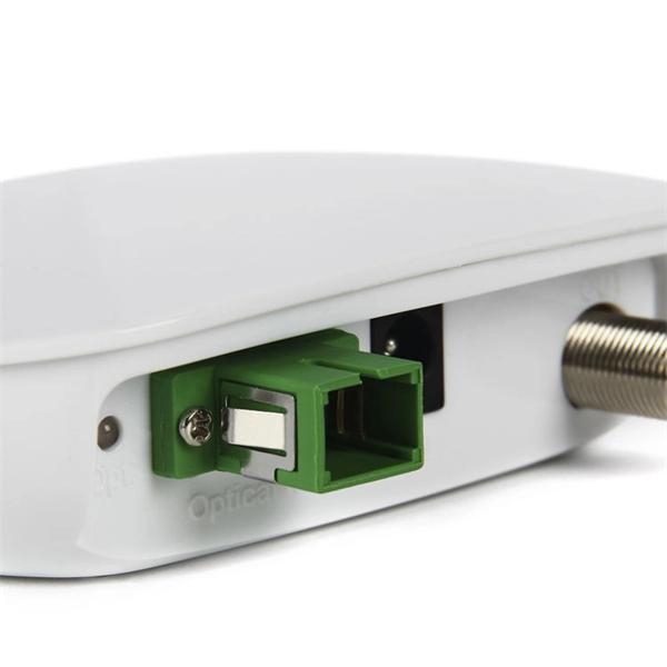
Insert a compatible SFP transceiver into the converter's port, making sure it matches the network's media type and speed. Then, connect one end of the fiber cable to the transceiver and the other to the appropriate port on a switch, router, or another media converter. Fiber media converters translate copper's electrical signals into fiber's optical signals, and back again. This allows networks to extend beyond the 100 m copper limit while gaining higher bandwidth and resistance to electromagnetic interference. In the illustrated setup, each LAN links to a. A fiber media converter is a networking device that allows you to convert a signal from one medium to another. This allows you to connect devices that use different types of cabling, such as a computer. While fiber optic ports are becoming increasingly common on networked electronics, the majority of connected devices still rely on RJ45 twisted pair connections. To help bridge the copper-fiber divide, media converters and transceiver modules (also known as SFPs or mini-GBICs) are often required. Use Fiber Media Converter in Your Network Media converters today are widely deployed in all. It is a device used to convert fiber optic cables to Ethernet cables to provide better connectivity. It is necessary to convert fiber optic signals to Ethernet signals because many network devices can only communicate with Ethernet signals. Fiber optic cables are known for the unmatched speed.
[PDF]
Use this worksheet to input values for all variables that will impact your system's performance. After entering your values, please ensure you click the 'Calculate Link Loss' button at the bottom of the page to generate your total link loss. Add connectors, splices, bends, and safety margin easily. See results instantly above the form, then adjust values. Choose a mode, then enter values and optional losses. All calculations use base-10 logarithms. mW must be greater than zero. Used only in measured attenuation mode. Length is needed. The power budget refers to the amount of fiber optic cable plant loss that a datalink (transmitter to receiver) can tolerate in order to operate properly. Sometimes the power budget has both a minimum and maximum value, which means it needs at least a minimum value of loss so that it does not. To detect whether the link runs properly, the following calculation should be performed. It is often the case to calculate the maximum signal loss across a given fiber link during optical cable installation. First, you should be aware of the fiber loss formula: The Total Link Loss = Cable. Therefore, it is very important to calculate the fiber loss and take appropriate steps. In order to get the most reliable results, an Optical Time Domain Reflectometer (OTDR) trace of the actual fiber connection should be completed. This will provide you with the real.
[PDF]
This article provides a detailed exploration of Fiber Amplifiers—what they are with regards to Fiber Cabling, how they function, their types, and their significance. Probably the most important application of fiber amplifiers is in optical fiber communications, i., data transmission through optical fibers., every 50 km of fiber. Based on their location and function within the fiber optic line, they are generally categorized as relay amplifiers, preamplifiers, and power amplif. more How to use a fiber. This article explains what optical amplifiers are, how optical amplifiers work, their main types, and why optical amplifiers are indispensable in modern fiber networks. What Is an Optical Amplifier? An optical amplifier is a device that increases the intensity of a light signal traveling through an. High Power Fiber Amplifiers (HPFAs) are critical components in modern optical systems, designed to boost weak optical signals into high-power outputs. Whether you're building long-distance communication links or powering high-intensity laser applications, HPFAs offer the performance, stability, and. Amplification can take place in two ways: the optical signal can be detected, converted to an electrical signal, then returned to the optical domain by modulating an optical source, or an amplifier that directly amplifies the optical signal can be used. The fiber is doped with rare earth elements, such as.
[PDF]