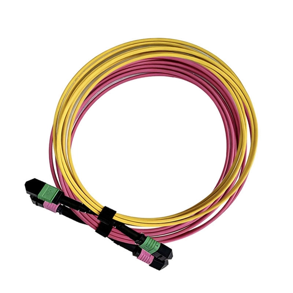
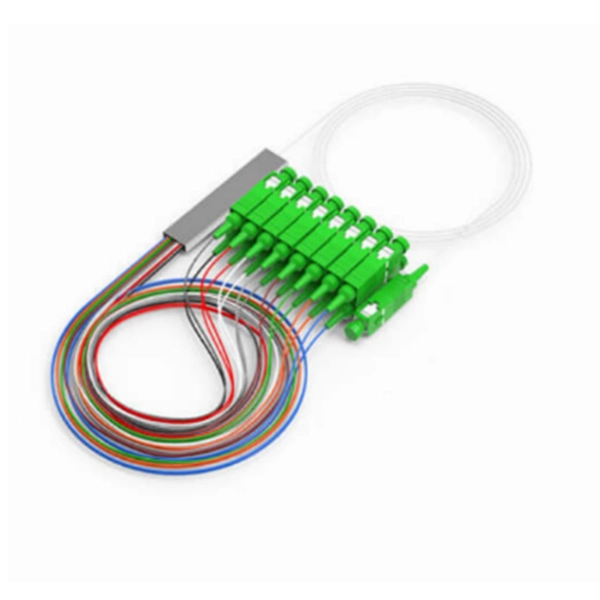
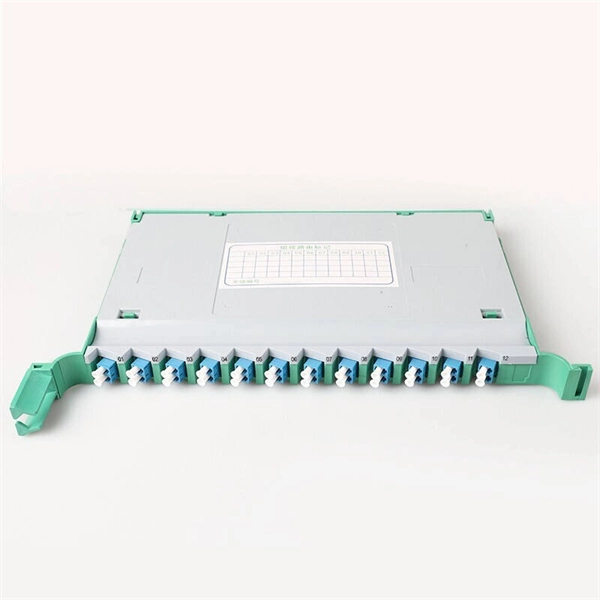
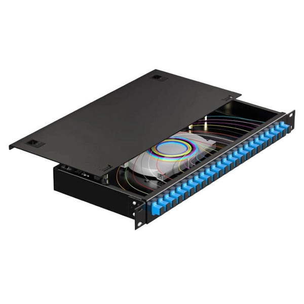
A PLC Splitter takes one optical signal and splits it into many outputs. This helps share signals in fiber optic networks. Pick the split ratio that matches what you need. Lower ratios work for fewer users. Choose the connector type like SC, LC, or FC. This. The optical splitter is an important passive device in the optical fiber link. It generally has one or two input ends and many outputs end for laser signal distribution. This article will explain the. Planar Lightwave Circuit (PLC) splitters play a vital role in modern fiber optic communication networks by enabling the efficient distribution of high-speed optical signals. It is one of the core components in Passive Optical Networks (PON) and is widely used in FTTx deployments, where a single fiber connection. This video provides a step-by-step guide on how to efficiently install optical splitter into a fiber terminal box, demonstrating a professional and reliable deployment for optical distribution network solution ( https://www. com/c/optical-distribu. more This video provides a step-by-step.
[PDF]
You can test a photocoupler with a multimeter. This checks if its output changes when you power its input. This gives you the most accurate test results. This detailed guide will walk you through the process of testing an optocoupler using a multimeter, covering various scenarios and providing practical advice to ensure accurate results and avoid common pitfalls. We'll explore the underlying principles, delve into different testing methods, and. In this episode #0018 of Electronic Components Testing, we reveal how to test an optocoupler (optoisolator) using a digital multimeter step by step. This simple yet powerful technique will help you detect faulty optocouplers on circuit boards without desoldering them. Always. What are the methods to test optocoupler? The quality of the optocoupler can be determined by measuring the forward and reverse resistance of its internal diode and triode. Jotrin Electronics Limited will tell you that the reliable detection methods,as follows: 1. From basic circuit design to complex industrial systems, accurate optocoupler. Optocoupler is one type of ICs, It isolates input and output section by using optical technology this feature increase safety of circuit. Optocoupler has many part number, different part number has different output type so before checking it has to use part number to research with datasheet and.
[PDF]
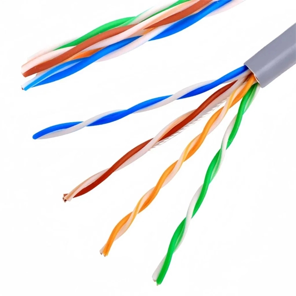
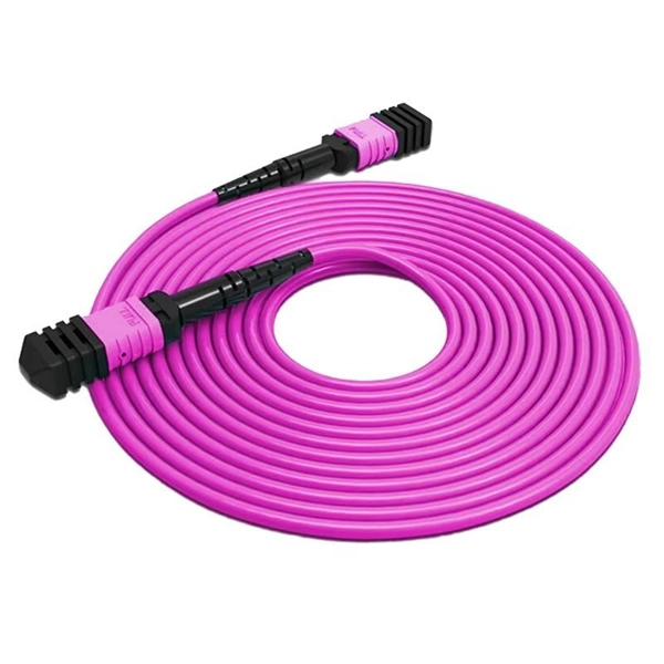
This interactive tutorial explores transmission and reflection of a light beam by three common beamsplitter designs. In addition to the task of dividing light, beamsplitters can be employed to recombine two separate light beams or images into a single path. The tutorial initializes with a cube. The fiber jumper connects the network devices at both ends and is used in the following three scenarios. FC Connector: use a metal sleeve for external reinforcement, fastened with a screw fastener. Generally used in the ODF (the most used on MDF) SC Connector: connected to the GBIC module, its. As title. It is a crucial part of many optical experimental and measurement systems, such as interferometers, also finding widespread application in fibre optic telecommunications. In its. The beam splitter has played numerous roles in many aspects of optics. For example, in quantum information the beam splitter plays essential roles in teleportation, bell measure-ments, entanglement and in fundamental studies of the photon. Electric elds E1 and E2 enter input ports 1 and 2. A beam splitter is an optical device that splits beams (such as laser beams) into two (or more) beams. Beam splitters typically come in the form of a reflective device that can split beams into exactly 50/50, half of the beam being transmitted through the splitter and half being reflected.
[PDF]
Press the Percent T/A selector to select Percent Transmittance or Percent Absorbance mode. Locate the wavelength dial beside the sample chamber and set it to the desired wavelength. Don gloves and wipe a cuvette with a lab wipe to clean it and remove any fingerprints. A spectrometer is an analytical tool used across various scientific disciplines to measure how a substance interacts with light. Specifically, a UV-Visible Spectrometer measures the absorption or transmission of light in the ultraviolet (UV) and visible (Vis) regions of the electromagnetic. How did a Spectrophotometer help scientists identify a species of bacteria that can clean up pollution? What is a Spectrophometer anyway, and how do you use one? In this video, Jayme Dyer answers these questions and provides practical Pro-Tips for how to use a Spectrophotometer in the lab. It consists of two parts: a spectrometer and a photometer. The spectrometer provides light at a specific wavelength. When you use spectrophotometry, you gain skills that help in many science fields. You will see that. Here's a step-by-step guide to using a spectrophotometer effectively. Blank Calibration: Fill a. Turn the Device on and Allow It to Warm Up 2. Clean and Prepare Containers and Control Samples 3. Standardize the Device According to Manufacturer's Directions 4. Choose Your Measurement Comparisons and Capture Data Spectrophotometric solutions simplify the science of quantifying chromatic data for.
[PDF]
This document describes how to use and program the Photonic Application Suite, Insertion Loss Engine. Insertion loss is measured by comparing signal power (or sound level) before and after it passes through a component or system, then expressing the difference in decibels (dB). The core process is the same across fiber optics, RF electronics, and acoustics: establish a baseline reference without. This tutorial aims to help RF engineers understand how to test and measure various RF specifications of RF power amplifiers, RF LNAs (Low-Noise Amplifiers), and RF transceivers using RF test and measurement equipment like spectrum analyzers, signal generators, and sweep oscillators. Gain is the. Coaxial cables are essential components in transmitting radio frequency (RF) signals, but they inherently attenuate these signals, a phenomenon known as cable loss or insertion loss. Yes, I would like to receive educational or promotional emails from Keysight. By clicking the button, you. Insertion loss is a critical parameter in RF engineering that refers to the loss of signal power that occurs when a component or device is inserted into a transmission line or circuit. The insertion loss measurement quantifies the effect of the resistance the cabling link offers to the transmission of the electrical signals. Insertion loss characteristics of a.
[PDF]

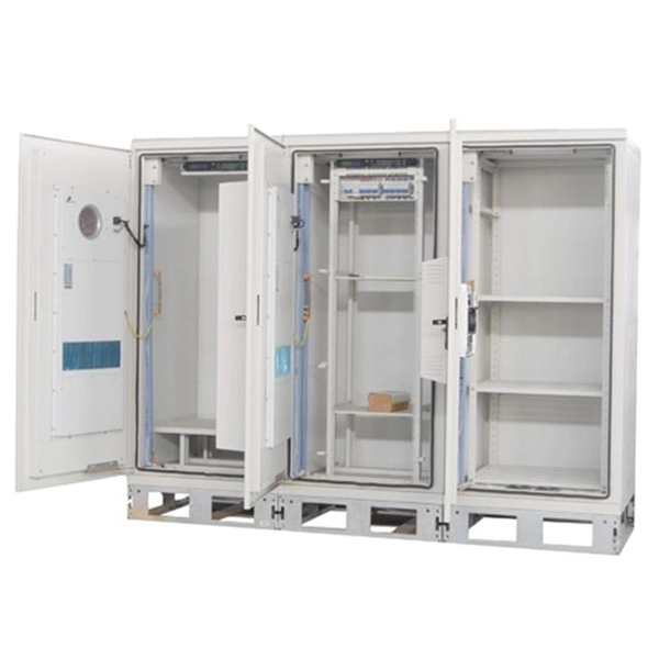
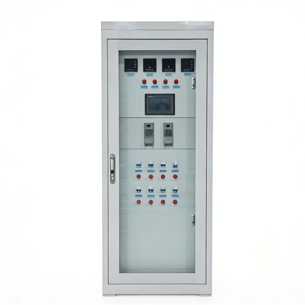
This document provides a comprehensive technical overview of the Ring Main Unit (RMU), serving as a reference for power system design, selection, and maintenance. Ring Main Units (RMU s) and Medium Voltage (MV) Switchgear are crucial in MV power distribution. Globally, they each hold about half the market share. MV switchgear handles primary distribution for large industrial facilities and grid infrastructure. RMUs, however, shine in secondary distribution. RMUs are commonly used in secondary distribution systems, particularly in urban areas, industrial complexes, and commercial. Scope of Application: The Ring Main Unit (RMU) is a compact switchgear device used in medium-voltage power distribution systems (typically 10kV–35kV). Some of the key features of the RMU includes SF6 gas insulation, compact and modular construction, integral protection system, fully extendable options. SFA-RM units are designed for supplying reliable energy, protecting electrical equipment in secondary distribution networks up to 17. Their compact design makes them suitable for various network applications such. Loading. Company Introduction:The New Concept Electric Inc. (NCE) was founded in October 2001, with a registered capital of 57 million Yuan. The company now covers an area of 77, 601 square meters (116 acres), and has a building area of 80, 451 square meters.
[PDF]
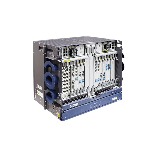
This article provides a detailed exploration of Fiber Amplifiers—what they are with regards to Fiber Cabling, how they function, their types, and their significance. Probably the most important application of fiber amplifiers is in optical fiber communications, i., data transmission through optical fibers., every 50 km of fiber. Based on their location and function within the fiber optic line, they are generally categorized as relay amplifiers, preamplifiers, and power amplif. more How to use a fiber. This article explains what optical amplifiers are, how optical amplifiers work, their main types, and why optical amplifiers are indispensable in modern fiber networks. What Is an Optical Amplifier? An optical amplifier is a device that increases the intensity of a light signal traveling through an. High Power Fiber Amplifiers (HPFAs) are critical components in modern optical systems, designed to boost weak optical signals into high-power outputs. Whether you're building long-distance communication links or powering high-intensity laser applications, HPFAs offer the performance, stability, and. Amplification can take place in two ways: the optical signal can be detected, converted to an electrical signal, then returned to the optical domain by modulating an optical source, or an amplifier that directly amplifies the optical signal can be used. The fiber is doped with rare earth elements, such as.
[PDF]
Definition of Protective Relay A protective relay is an automatic device that detects abnormalities in an electrical circuit and closes its contacts. This action completes the circuit breaker's trip coil circuit, causing the breaker to trip and disconnect the faulty section from the. Eaton's protective relays provide you with unique microprocessor-based devices that eliminate unnecessary trips, mitigate arc faults, protect motors and breakers, and provide system information to help you better manage your system. Our predictive diagnostic solutions include non-destructive testing. Here, Several circuit breakers in the fault current paths from the generators to the fault location have been tripped. Note that all generators- the power sources – have been disconnected. Therefore, the whole system has gone down, even though many circuit breakers have remained closed. The relay continuously monitors electrical parameters such as current, voltage, frequency, and phase angle. When these parameters deviate from normal operating conditions or. The rectangular devices are test connection blocks, used for testing and isolation of instrument transformer circuits. : 4 The first protective relays were electromagnetic. Protective Relays - Technical Seminar Nov 2016 - Copyright: IEEE 2 Abstract: Protective relays and devices have been developed over 100 years ago to provide “lastline”of defense for the electrical systems.
[PDF]
This document provides the users of USB4000 Spectrometers with instructions for setting up, calibrating and performing experiments with their spectrometer. Remote fiber optic spectroscopy is a sophisticated technique that uses fiber optic couplers, cables, and accessories to analyze samples at a distance from the spectrophotometer. The technique unlocks a range of experiments that standard UV-Vis or fluorescence instruments cannot accommodate. The. Fiber optic spectrometers have revolutionized the field of remote sensing and data acquisition, providing unprecedented flexibility and precision. These devices utilize the unique properties of fiber optics to measure and analyze the spectral composition of light, making them indispensable tools in. The Cary 60 Fiber Optic Coupler and the Cary 60 Dip Probe Coupler are optional accessories for the Cary 60 UV-Vis spectrophotometer. Both accessories convert the Cary 60 UV-Vis into a remote fiber optic measurement system. Contains descriptive. Near-Infrared Spectroscopy (NIR) offers important advantages in analytical chemistry, particularly in process monitoring and quality control across various industries. This paper details the operational principles, methodologies, and significant advancements in NIR spectroscopy, emphasizing the. The basics of fiber optic cables and bundles and how they can be used to collect and direct light are discussed in 'An Introduction to a Spectrometer: Fiber Optic Bundles'.
[PDF]
High voltage relays are essential components in electrical systems. They control the flow of electricity in high voltage applications, enabling safe operations. These relays act as switches that open or close circuits. Their design ensures they handle high current levels without. Explore principles and configurations of protective relaying in high voltage systems. Ensure fast, selective fault clearance per IEC/IEEE standards. Protective relaying is the backbone of fault detection and system isolation in As transmission systems grow increasingly complex with integration of. A voltage protection relay system is a necessary component of any electrical setup. It prevents safety hazards and damage to equipment. It monitors voltage to determine if levels rise too high or dip too low. Many industries use voltage protection relay systems, especially those in high-voltage. Eaton's protective relays provide you with unique microprocessor-based devices that eliminate unnecessary trips, mitigate arc faults, protect motors and breakers, and provide system information to help you better manage your system. Our predictive diagnostic solutions include non-destructive testing. In electrical engineering, a protective relay is a relay device designed to trip a circuit breaker when a fault is detected. They are intended to quickly identify a fault and isolate it so the balance of the system continue to run under normal conditions.
[PDF]
What is the cost of a relay coordination study in Singapore ? The cost of a protective device study in Singapore depends on the complexity of the electrical system, facility size, and number of relays. I2R, as a firm of Professional Engineers and Licensed Electrical Workers, is qualified under the Electricity Act to carry out all types of electrical testing and commissioning works to ensure that electrical apparatus are fit for power energization and safe for use and operation. We have all the. We are Specialized in Low Voltage Switchgears Testing, Commissioning, Maintenance and Installations from OEM's. We do factory Acceptance and Site Acceptance Testing and Commissioning support of LV Switchgears. Earth loop impedance measurments. Care Offers cost-effective solutions for protective device coordination in compliance with. Advance Engineering and Testing (AET) Pte Ltd established on 2019, is a top provider of electrical testing ranging from commercial, domestic, and industrial. The company provides 24/7 onsite support with prioritization of customer satisfaction. Their vision and mission statement is to continuously. The type of testing required for each specific relay needs to be designed with the goal of accomplishing the objective. We perform testing in four specific classes which. Our services are applicable to a number of industries such as Petrochemical industries, Oil and gas fabrication industries, Wafer fabrication plants, Pharmaceuticals.
[PDF]
It works on the principle of sensing residual current which is why it is called a residual current device. Nowadays, all domestic and commercial electrical systems and circuits use RCDs. Today, we will see how you can connect an RCD to the distribution . Hey, in this article we are going to see the RCD Wiring diagram and its connection procedure. RCD means Residual Current Device. It is an electrical protective device that protects electrical circuits and devices from some electrical faults such as leakage faults, electrical shock, current. Distribution board is a safe system designed for house or building that included protective devices, isolator switches, circuit breaker and fuses to connect safely the cables and wires to the sub circuits and final sub circuits including their associated Live (Phase) Neutral and Earth conductors. Residual-current devices, commonly referred to as RCDs, are used in many practical applications. They can be found in fuse boxes, electrical switchgears or industrial machine control systems. Therefore. A distribution box uses MCBs, RCDs, and busbars to protect circuits, prevent shocks, and ensure safe power distribution in homes and buildings. This box keeps your home or building safe from electrical dangers. Devices that operate with electricity can cause leakage due to various reasons. If this leakage is not detected and cut off in time, it can lead to.
[PDF]
In this guide, we'll walk you through the essential steps to maximize the benefits of your power distribution box. Converts high voltage into safe, usable outputs for various applications. Essential for industries like construction, disaster recovery, and entertainment. Whether you are an electrical contractor or a construction brigade, knowing how to properly and safely install distribution boxes is the basis of ensuring the safe operation of the entire system. This article details the process of installing them, which helps you comprehend distribution boxes. In modern electrical systems, cable distribution boxes (also known as electrical distribution boxes or distribution boxes) play a crucial role as the key hub for managing, distributing, and protecting circuits. more Welcome to our channel! In this video. An electrical panel box, also known as a breaker box or a distribution board, is a crucial component of any electrical system. It serves as a central hub for distributing electricity throughout a building, ensuring that power is delivered safely and efficiently to all the required locations. These units are equipped with GFCI protection, ensuring safety across diverse applications 1.
[PDF]
This video makes connecting your fiber optic cable to your router a breeze! We'll guide you through the entire process step-by-step, ensuring a smooth and hassle-free experience. Our Experts are helping user's, who are facing issues with their tech gadgets like Router . In this guide, we'll walk you through how to connect a fiber optic cable to a router safely and efficiently. Why Use Fiber Optic Internet? Before diving into the setup, let's quickly recap why fiber optics are worth the effort: Lightning-fast speeds (up to 1 Gbps or higher). If you. The fiber optic cable does not plug directly into a standard home router because the signal type must be translated. The fiber line terminates at the Optical Network Terminal (ONT), which is typically supplied and installed by the internet service provider. This comprehensive guide combines industry standards with field-tested practices to ensure you achieve a rock-solid. Turn on the router; 2. Plug one end of the network cable into either of the router's ports and the other end into the Internet wall socket or the LAN port of an optical modem or ADSL modem. Does it help? Copyright © 2010 - 2026 Xiaomi. Check compatibility: Before you begin, make sure your router supports fiber optic connection. Not all routers can connect directly to a fiber cable, so it is important to verify this information before continuing.
[PDF]
If your ISP doesn't require a technician to set up your connection, these are the steps to self-install fiber internet: Locate your fiber network terminal. Connect the fiber terminal to the network box. Connect your device to the network. Self-install is pretty straightforward--it's similar to getting a new tv, game console, tablet or computer out of the box and setting it up on your own. If you (or someone in your home) are comfortable with that, you'll be able to install and set up your TDS service. However, there are a couple of. The service box (Optical Network Terminal/ ONT) brings AT&T Internet into your home. Once you locate it (may be in basement, utility closet or garage), remove cover and connect: GREEN fiber connector to GREEN PON port (if not already connected). Post-installation optimization matters —proper router placement, firmware updates, and network security configuration maximize your fiber internet investment. 65% of. Whether you go for an indoor or outdoor installation can impact your internet's reliability, speed and even how easy it is to troubleshoot issues. Let's break it all down, so you can make an informed choice and get the most out of your fiber experience. To install your broadband, you only need to understand a few basic steps. Most DSL services provide a modem, router, filters, cables, and self-installation manual. If you have a home phone, connect the.
[PDF]