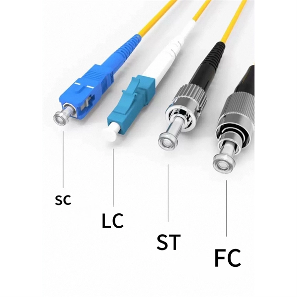
This interactive tutorial explores transmission and reflection of a light beam by three common beamsplitter designs. In addition to the task of dividing light, beamsplitters can be employed to recombine two separate light beams or images into a single path. The tutorial initializes with a cube. The fiber jumper connects the network devices at both ends and is used in the following three scenarios. FC Connector: use a metal sleeve for external reinforcement, fastened with a screw fastener. Generally used in the ODF (the most used on MDF) SC Connector: connected to the GBIC module, its. As title. It is a crucial part of many optical experimental and measurement systems, such as interferometers, also finding widespread application in fibre optic telecommunications. In its. The beam splitter has played numerous roles in many aspects of optics. For example, in quantum information the beam splitter plays essential roles in teleportation, bell measure-ments, entanglement and in fundamental studies of the photon. Electric elds E1 and E2 enter input ports 1 and 2. A beam splitter is an optical device that splits beams (such as laser beams) into two (or more) beams. Beam splitters typically come in the form of a reflective device that can split beams into exactly 50/50, half of the beam being transmitted through the splitter and half being reflected.
[PDF]
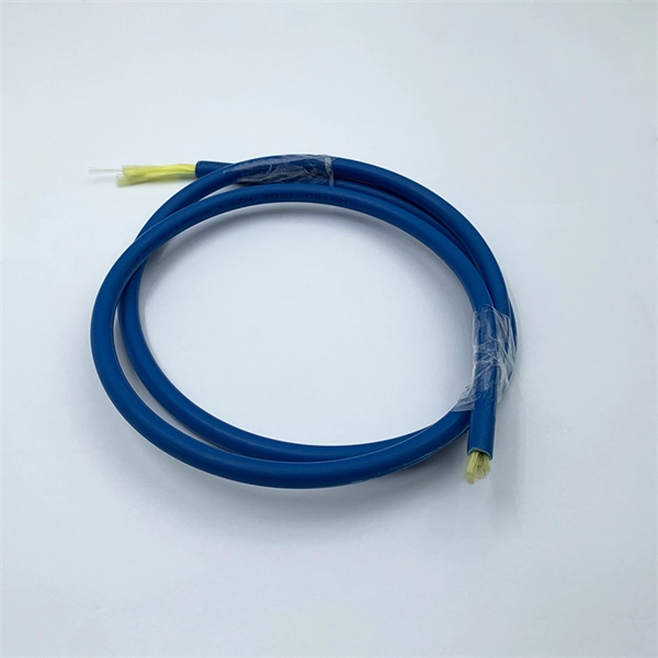
Fiber Connection: Locate the optical port on your router and carefully insert the fiber cable's connector, ensuring a snug fit. Click it into place if it has a locking mechanism. Power Up: Connect the power cords to your router and any additional devices (ONT, media converter) and. Proper connection of fiber optic cables is essential to harness these benefits fully, as even minor errors can lead to significant performance issues like signal loss. This article will guide you through the necessary tools, materials, and methods on how to connect fiber optic cables effectively. Fiber optic internet delivers blazing-fast speeds and reliable connectivity, making it a top choice for modern homes and businesses. However, setting up a fiber optic connection to your router can seem daunting if you're unfamiliar with the process. Before you start, gather the right tools. You don't want to dig around mid-job for something small but essential. Each tool helps you protect the fiber. The process to connect fiber optic cable to router requires careful attention to detail, but I'll walk you through every critical step with the precision and clarity you deserve. The fiber. The process involves a combination of national infrastructure, local engineering, and property-level setup. In this guide, we'll break down the fiber installation process from start to finish and explain key components such as fiber cabinets, flower pods, ducting, and ONT setup. What Is Fiber Optic.
[PDF]
This video makes connecting your fiber optic cable to your router a breeze! We'll guide you through the entire process step-by-step, ensuring a smooth and hassle-free experience. Our Experts are helping user's, who are facing issues with their tech gadgets like Router . In this guide, we'll walk you through how to connect a fiber optic cable to a router safely and efficiently. Why Use Fiber Optic Internet? Before diving into the setup, let's quickly recap why fiber optics are worth the effort: Lightning-fast speeds (up to 1 Gbps or higher). If you. The fiber optic cable does not plug directly into a standard home router because the signal type must be translated. The fiber line terminates at the Optical Network Terminal (ONT), which is typically supplied and installed by the internet service provider. This comprehensive guide combines industry standards with field-tested practices to ensure you achieve a rock-solid. Turn on the router; 2. Plug one end of the network cable into either of the router's ports and the other end into the Internet wall socket or the LAN port of an optical modem or ADSL modem. Does it help? Copyright © 2010 - 2026 Xiaomi. Check compatibility: Before you begin, make sure your router supports fiber optic connection. Not all routers can connect directly to a fiber cable, so it is important to verify this information before continuing.
[PDF]
The fastest way to test a fluorescent tube is with a multimeter set to continuity mode. Each end of the tube has two pins connected by a thin filament inside the glass. If either filament is broken, the tube is dead. The whole test takes about 30 seconds per tube once you know what. Knowing how to use a multimeter to check an LED tube light is a valuable skill for homeowners, electricians, and anyone involved in maintaining lighting systems. Perhaps it's a simple wiring problem, a. One essential tool for diagnosing LED tube light issues is a multimeter. This process measures electrical resistance to determine if the tube has suffered an internal failure before replacing the bulb or investigating the ballast. If you don't have a multimeter to use, a simple coin cell battery holder with leads will let you know. Yes, you absolutely can test an LED light with a multimeter! It's a straightforward process that helps you figure out if your LED is working or if it's the source of a problem in your circuit.
[PDF]
This document provides the users of USB4000 Spectrometers with instructions for setting up, calibrating and performing experiments with their spectrometer. Remote fiber optic spectroscopy is a sophisticated technique that uses fiber optic couplers, cables, and accessories to analyze samples at a distance from the spectrophotometer. The technique unlocks a range of experiments that standard UV-Vis or fluorescence instruments cannot accommodate. The. Fiber optic spectrometers have revolutionized the field of remote sensing and data acquisition, providing unprecedented flexibility and precision. These devices utilize the unique properties of fiber optics to measure and analyze the spectral composition of light, making them indispensable tools in. The Cary 60 Fiber Optic Coupler and the Cary 60 Dip Probe Coupler are optional accessories for the Cary 60 UV-Vis spectrophotometer. Both accessories convert the Cary 60 UV-Vis into a remote fiber optic measurement system. Contains descriptive. Near-Infrared Spectroscopy (NIR) offers important advantages in analytical chemistry, particularly in process monitoring and quality control across various industries. This paper details the operational principles, methodologies, and significant advancements in NIR spectroscopy, emphasizing the. The basics of fiber optic cables and bundles and how they can be used to collect and direct light are discussed in 'An Introduction to a Spectrometer: Fiber Optic Bundles'.
[PDF]
Press the Percent T/A selector to select Percent Transmittance or Percent Absorbance mode. Locate the wavelength dial beside the sample chamber and set it to the desired wavelength. Don gloves and wipe a cuvette with a lab wipe to clean it and remove any fingerprints. A spectrometer is an analytical tool used across various scientific disciplines to measure how a substance interacts with light. Specifically, a UV-Visible Spectrometer measures the absorption or transmission of light in the ultraviolet (UV) and visible (Vis) regions of the electromagnetic. How did a Spectrophotometer help scientists identify a species of bacteria that can clean up pollution? What is a Spectrophometer anyway, and how do you use one? In this video, Jayme Dyer answers these questions and provides practical Pro-Tips for how to use a Spectrophotometer in the lab. It consists of two parts: a spectrometer and a photometer. The spectrometer provides light at a specific wavelength. When you use spectrophotometry, you gain skills that help in many science fields. You will see that. Here's a step-by-step guide to using a spectrophotometer effectively. Blank Calibration: Fill a. Turn the Device on and Allow It to Warm Up 2. Clean and Prepare Containers and Control Samples 3. Standardize the Device According to Manufacturer's Directions 4. Choose Your Measurement Comparisons and Capture Data Spectrophotometric solutions simplify the science of quantifying chromatic data for.
[PDF]
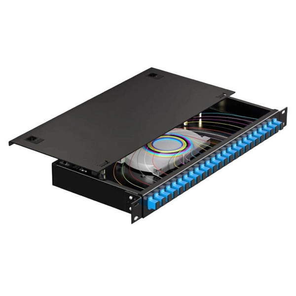
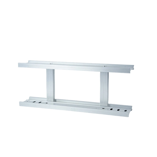
This complete guide explores everything you need to know about ODFs — from their structure, types, and key components, to installation best practices and modern design trends. Whether you're building a central office, data center, or FTTx distribution network, understanding the right ODF. In the complex architecture of fiber optic networks, the Optical Distribution Frame (ODF) serves as the linchpin for organizing, protecting, and distributing optical signals. It's where incoming and outgoing cables meet. It does four key things: Think of it as the central hub for your fiber network. Without it, cables get tangled. All. How to Splice 4-Fiber Optic Cable with ODF | Step-by-Step Fiber Optic Splicing Tutorial. Whether you are a beginner or a professional in fiber optic networking, this guide will help you splice. Fiber Optic Infrastructure Specialist (19Y Exp) | One-Stop: Fiber Cables, Distribution Boxes, Splice Closures, Splitters & Patch Cords | Sourcing for ISPs & Contractors in EU/Africa. It is used to terminate, connect, and distribute optical fibers, and it can be installed in various environments such as data centers, telecom rooms, and central offices. In this article.
[PDF]
This document describes how to use and program the Photonic Application Suite, Insertion Loss Engine. Insertion loss is measured by comparing signal power (or sound level) before and after it passes through a component or system, then expressing the difference in decibels (dB). The core process is the same across fiber optics, RF electronics, and acoustics: establish a baseline reference without. This tutorial aims to help RF engineers understand how to test and measure various RF specifications of RF power amplifiers, RF LNAs (Low-Noise Amplifiers), and RF transceivers using RF test and measurement equipment like spectrum analyzers, signal generators, and sweep oscillators. Gain is the. Coaxial cables are essential components in transmitting radio frequency (RF) signals, but they inherently attenuate these signals, a phenomenon known as cable loss or insertion loss. Yes, I would like to receive educational or promotional emails from Keysight. By clicking the button, you. Insertion loss is a critical parameter in RF engineering that refers to the loss of signal power that occurs when a component or device is inserted into a transmission line or circuit. The insertion loss measurement quantifies the effect of the resistance the cabling link offers to the transmission of the electrical signals. Insertion loss characteristics of a.
[PDF]
A spectrophotometer is a piece of spectroscopy equipment measures the amount of light absorbed by a sample. This measurement can be useful in many research applications: To identify materials by mapping molecular absorption profiles. To work out solute concentrations in solutions. Specifically, a UV-Visible Spectrometer measures the absorption or transmission of light in the ultraviolet (UV) and visible (Vis) regions of the electromagnetic. A spectrometer is a scientific instrument that analyzes light to reveal information about materials. It functions by separating light into its constituent wavelengths, much like a prism splits sunlight into a rainbow. This analytical capability makes spectrometers valuable tools across many fields. Spectrophotometry is an experimental technique that is used to measure the concentration of solutes in a specific solution by calculating the amount of light absorbed by those solutes. It is widely used in laboratories to analyze various substances, from liquids to gases. Here's a step-by-step guide on how to use a spectrophotometer. When you use spectrophotometry, you gain skills that help in many science fields. This guide makes spectroscopy simple by showing you how to use teaching tools and real experiments. The basic principle is that each compound absorbs or transmits light over a certain range of wavelength. This measurement can.
[PDF]
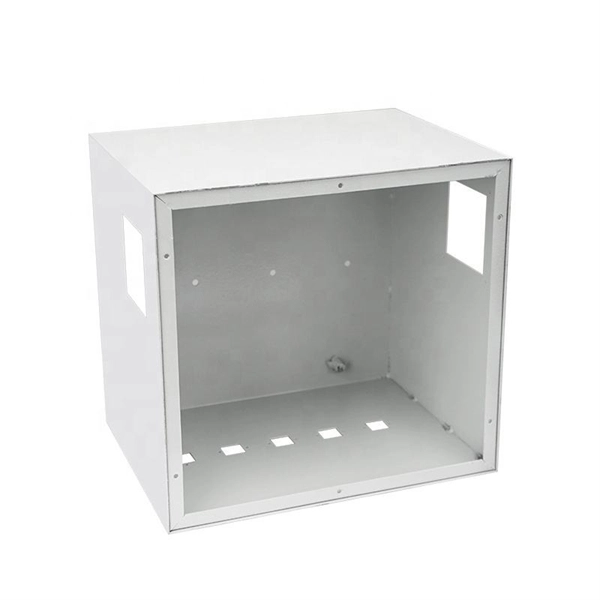
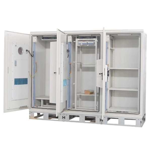
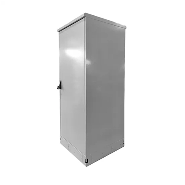
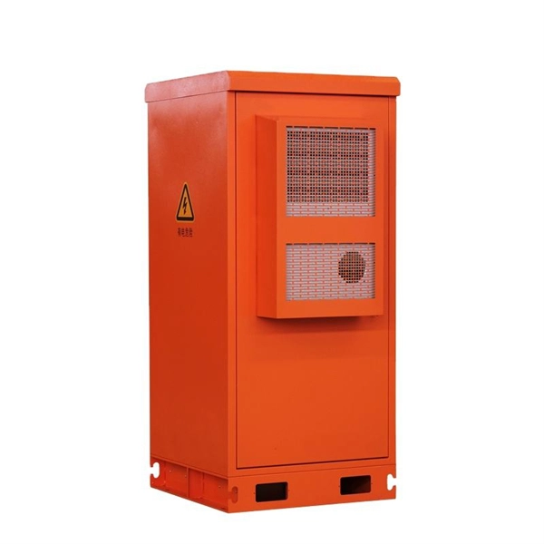
In this guide, we'll walk you through the essential steps to maximize the benefits of your power distribution box. Converts high voltage into safe, usable outputs for various applications. Essential for industries like construction, disaster recovery, and entertainment. Whether you are an electrical contractor or a construction brigade, knowing how to properly and safely install distribution boxes is the basis of ensuring the safe operation of the entire system. This article details the process of installing them, which helps you comprehend distribution boxes. In modern electrical systems, cable distribution boxes (also known as electrical distribution boxes or distribution boxes) play a crucial role as the key hub for managing, distributing, and protecting circuits. more Welcome to our channel! In this video. An electrical panel box, also known as a breaker box or a distribution board, is a crucial component of any electrical system. It serves as a central hub for distributing electricity throughout a building, ensuring that power is delivered safely and efficiently to all the required locations. These units are equipped with GFCI protection, ensuring safety across diverse applications 1.
[PDF]
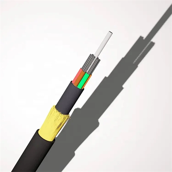
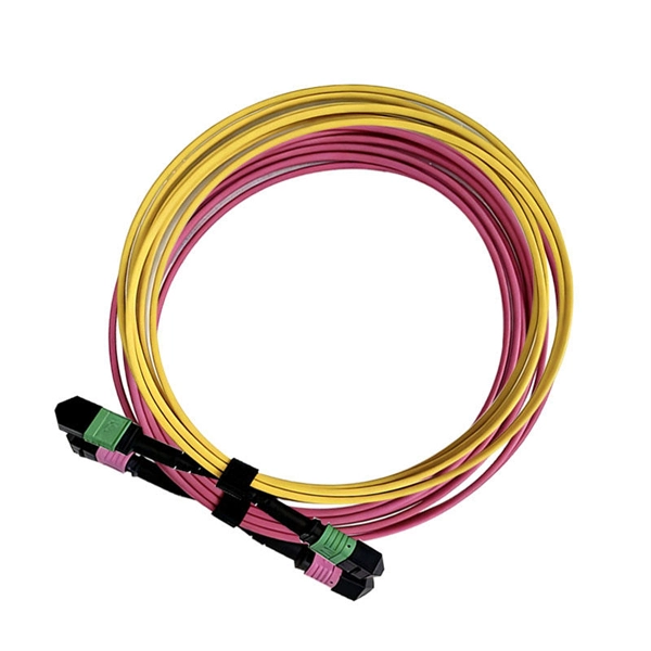
This guide reveals the secrets to fusion splicing with little fluff—just proven, straightforward techniques refined from years of work in the field. In this guide, you will find a chronological description of the fusion splicing process, the principal technical standards, and answers to the real-life questions network engineers and procurement teams may have. The guide provides the complete workflow, covering safety precautions, tool selection, fiber preparation, fusion operation, quality control, and. Summary: Fiber color codes, defined by the TIA-598-C standard, help technicians quickly identify individual fibers, buffer tubes, and connectors in multi-strand cables. Using proper color coding makes installation easier, speeds up troubleshooting, reduces downtime, and supports future network. When a tech opens a fiber optic cable to prepare it for splicing, they will find a colorful bundle of buffer tubes as on this armored cable. The colors of the buffer tubes and likewise the fibers in the tubes provide the identification the tech needs to complete the splicing of the fibers as the. Fusion splicing is the bedrock of high-performance fiber optic networks, enabling seamless signal transmission through permanent, low-loss fiber joins. By adopting the TIA/EIA‑598C standard, you gain a universal “language” of colors that speeds identification, reduces miswiring, and enhances safety.
[PDF]
A PLC Splitter takes one optical signal and splits it into many outputs. This helps share signals in fiber optic networks. Pick the split ratio that matches what you need. Lower ratios work for fewer users. Choose the connector type like SC, LC, or FC. This. The optical splitter is an important passive device in the optical fiber link. It generally has one or two input ends and many outputs end for laser signal distribution. This article will explain the. Planar Lightwave Circuit (PLC) splitters play a vital role in modern fiber optic communication networks by enabling the efficient distribution of high-speed optical signals. It is one of the core components in Passive Optical Networks (PON) and is widely used in FTTx deployments, where a single fiber connection. This video provides a step-by-step guide on how to efficiently install optical splitter into a fiber terminal box, demonstrating a professional and reliable deployment for optical distribution network solution ( https://www. com/c/optical-distribu. more This video provides a step-by-step.
[PDF]
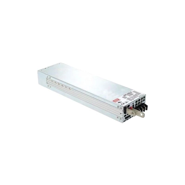
This article provides a detailed exploration of Fiber Amplifiers—what they are with regards to Fiber Cabling, how they function, their types, and their significance. Probably the most important application of fiber amplifiers is in optical fiber communications, i., data transmission through optical fibers., every 50 km of fiber. Based on their location and function within the fiber optic line, they are generally categorized as relay amplifiers, preamplifiers, and power amplif. more How to use a fiber. This article explains what optical amplifiers are, how optical amplifiers work, their main types, and why optical amplifiers are indispensable in modern fiber networks. What Is an Optical Amplifier? An optical amplifier is a device that increases the intensity of a light signal traveling through an. High Power Fiber Amplifiers (HPFAs) are critical components in modern optical systems, designed to boost weak optical signals into high-power outputs. Whether you're building long-distance communication links or powering high-intensity laser applications, HPFAs offer the performance, stability, and. Amplification can take place in two ways: the optical signal can be detected, converted to an electrical signal, then returned to the optical domain by modulating an optical source, or an amplifier that directly amplifies the optical signal can be used. The fiber is doped with rare earth elements, such as.
[PDF]
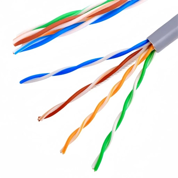
In this guide, we will walk you through the process of setting up a network switch, from selecting the right equipment to connecting and testing the network. Ethernet switches, also called network switches, connect multiple devices via Ethernet cables. In contrast, a router connects your local area network (LAN) to the internet's. A practical, current guide to planning, pulling and terminating Cat6/Cat6A cable — tools, techniques, testing and labeling for reliable results. By Thomas McCormack • Updated Mar 17, 2026 • 12 min read • Lead Technician and Engineer, Data Wire Solutions Disclosure: Some links may be affiliate. With an Ethernet cable, you can hardwire your devices to your network, providing fast and efficient. Your ethernet switch doesn't come with any ethernet cables, so you want to have some on hand when setting up your switch. You'll need one cable to connect your ethernet switch and router together (assuming you want to provide your devices with an ethernet connection to the internet), and an. A network switch is a crucial component in any modern network, enabling seamless communication between devices. By the end of this tutorial. Connecting a network switch involves physically connecting devices using Ethernet cables and configuring them as needed, ultimately expanding your network connectivity and improving network performance. Connecting a network switch is a foundational skill for anyone managing a home or small business.
[PDF]
A neat, well-organized subpanel bundles wires to conserve space and improve access. Ideally, wire groups are installed in layers and wires are bent at right angles to buses or breakers. Label short sheathing sections (slugs) to indicate which circuits wires serve. Choose the right box based on environment (indoor/outdoor), load capacity, and durability. Check for proper IP/NEMA ratings and material quality. Ensure safe placement: install in dry, accessible areas with good ventilation and at appropriate height (typically ~1. Practice good wiring: secure. Box installation: Make sure that Distribution box has been correctly installed and fixed. Material preparation: Prepare the required circuit breakers, wires, wiring ties and other materials, and ensure that they meet the design drawings and installation requirements. And all the switching and protective devices are installed in the. Wiring distribution panels serve as the central hub and nerve center, routing power from the main service feed to multiple circuits. When setting up such a significant component of industrial, commercial, and utility applications, it's essential to get everything right. Labeling cables at outlets is.
[PDF]