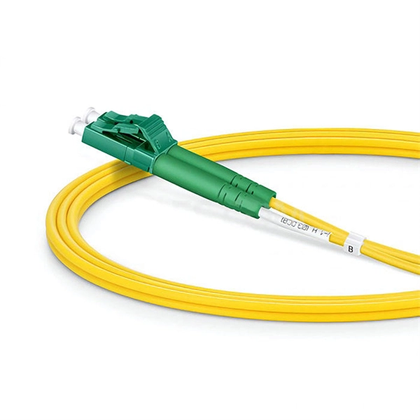
In this guide, you will find a chronological description of the fusion splicing process, the principal technical standards, and answers to the real-life questions network engineers and procurement teams may have. Splicing fiber optic cable is an extremely important phase for making dependable, high-speed communication infrastructures. Regardless of the type of fiber network you're deploying, be it for telecom, enterprise data centers, or smart city infrastructure, fusion splicing provides the benefits of. This is where fiber optic cable splicing—the process of creating a permanent, high-performance join between two fiber ends—becomes critical. For network managers and technicians, a poor splice can lead to significant signal degradation, network downtime, and costly troubleshooting. At Turn-Key. So in essence, fiber optic splicing is a process used to join two separate fiber optic cables together. There are numerous use cases for fiber optic splicing. Ensure Your Splicing Tools are Clean – #2. And tools used for fiber fusion: fusion splicer; fiber cleaver; cable stripper; fiber optic stripper; alcohol;. Splicing with fusion splicers, in particular, has become an attractive method to quickly and easily connect fiber optic fibers. Using the proper tool allows to connect the individual fibers of fiber optic cables extremely professionally. However, there are a few points to keep in mind during the.
[PDF]
Below is a detailed comparison table of typical optical module speeds ranging from 1G to 400G, highlighting wavelength, reach, power budget, connector type, data rate, and operating temperature. Optical modules, also known as transceivers, convert electrical signals to optical signals and vice versa. They come in multiple speed grades standardized by IEEE 802. 3, enabling data rates from 1 Gbps (Gigabit Ethernet) up to 400 Gbps (400G Ethernet). The choice of module speed directly impacts. We provide an industrial-grade reference framework, complying with the latest MSA (Multi-Source Agreement) updates, including SFF-8679 Rev 1. 4 (Jan 2025), to help you design robust, scalable optical fabrics. The Master Reference Matrix: SFP vs. QSFP Standards (2025 Edition) This table. Upgrade to 100G or 400G optics and save. Cisco Transceiver Modules - Learn product details such as features and benefits, as well as hardware and software specifications. How does our search work? With MEET OPTICS search you get direct access to our database of thousands of optical components from providers worldwide. com, we specialize in Cisco-compatible and NS Comm transceivers, offering enterprise customers tested, certified. SFP (Small Form-factor Pluggable) is a compact, hot-pluggable network interface module used to connect network devices (switches, routers, firewalls) to fiber optic or copper cables.
[PDF]
Huawei OLT Comparison: MA5600T vs MA5800 vs EA5800. This guide explains the architectural differences, PON technologies (GPON, XGS-PON), and helps you choose the right OLT for FTTx networks. MA5603T is multi service based while MA5683T is just OLT, MA5603T can support service like ADSL, VDSL, GPON etc, while MA5683T only supports GPON, P2P etc, but their hardware and configuration command is the same. MA5683T vs MA5680T? The only difference is capacity, MA5683T max support 6 service. Hi, This is ISP-Home. com, we excel in delivering high-performance fiber optical products, connecting you to a world of precision and reliability. As optical fiber access nodes keep moving closer to end users, OLTs are closer to end users. Deployment scenarios are complex and diversified. In this case, network needs OLTs with small volume and low density. The MA5801 series OLT is a compact and. When selecting a Huawei OLT (Optical Line Terminal), prioritize models that support your required number of subscribers, offer scalable GPON or XGS-PON technology, and integrate seamlessly with existing Huawei ONTs. For most mid-sized service providers, the MA5600T or MA5800-X17 provides the best. OLT Series: Access product manuals, HedEx documents, product images and visio stencils. The MA5800 is the industry's first smart aggregation OLT with a distributed architecture. It is positioned as the next-generation OLT for NG-PON.
[PDF]
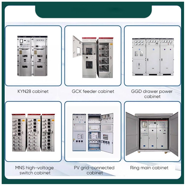
This comprehensive guide will cover the step-by-step installation methodology for power-electrical bus bars, emphasizing safety measures and best practices. Bus bars play a crucial role in electrical distribution systems by providing a reliable and efficient way to conduct electricity within electrical panels. Whether in industrial, commercial, or residential applications, bus bars in electrical panels enhance power distribution, reduce wiring. Busbars are the unsung heroes of electrical panels, ensuring reliable power distribution and minimizing clutter. If you've ever wondered how to achieve a flawless busbar installation, you're in the right place. This guide will walk you through every step of the process, from selecting the right. Ever wondered how busbars, the unsung heroes of electrical distribution, are processed and installed? This article delves into the intricate steps of busbar selection, preparation, and installation, ensuring efficient and safe power distribution. You'll discover the essential tools and techniques. This prevents the parts from moving and causing a dangerous short circuit. It is a very reliable way to move energy. Most are made of copper or aluminum because these metals carry current well. The busbar shims and hardware bag in the cubicle packaging. Refer to Access to the Busbar Compartments.
[PDF]
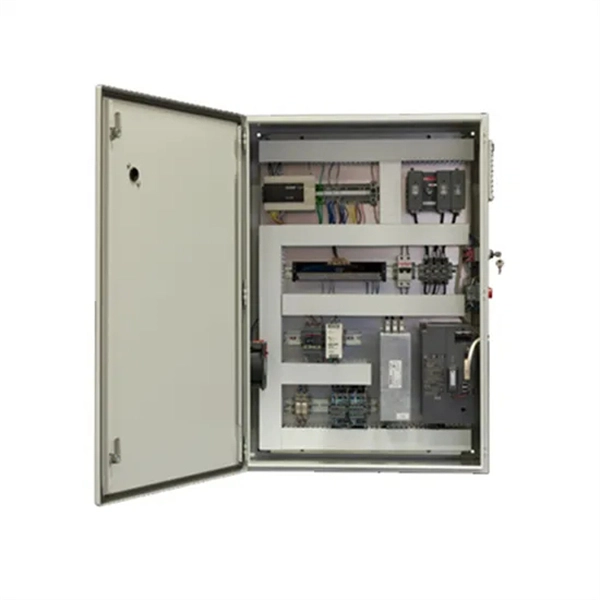
Take the appropriate rating of MCB and RCCB as per your load requirements. Identify the Input and Output sides of the MCBs and RCCBs. Connect the output of the Main MCB to the input. Primary distribution systems consist of feeders that deliver power from distribution substations to distribution transformers. A feeder usually begins with a feeder breaker at the distribution substation. Many feeders leave substation in a concrete ducts and are routed to a nearby pole. At this. Connection method: Each switch takes a wire from the incoming point and connects it to the incoming end of the switch, or uses parallel connection to reduce the difficulty of wiring. Wiring Direction: Wiring between the main circuit breaker and each branch circuit breaker in the box generally. Correct wiring methods for circuit breakers within distribution boxes are fundamental to ensuring electrical safety and compliance with established codes. The distinction between 1P and 2P circuit breakers plays a pivotal role in determining the appropriate protection level for various circuits. A primary distribution substation is the connection point of a distribution system to a trans-mission or a sub-transmission network. This guide shows you how to organize circuit breaker wiring properly. You will learn to build a safe, efficient, and professional electrical system today. Circuit breaker wiring configurations involve organizing main switches, busbars.
[PDF]
Surge protection is very important now because new buildings have more sensitive electronics and need power all the time. Put SPDs near the main busbar. This keeps wires short. Short wires help protect devices better. Use Type 2 SPDs in most. It is very important to follow the manufacturer's installation instructions. Pay particular attention to fuse or breaker requirements and lead lengths. Failure to do so may result. Today, this article will systematically explain the wiring methods and installation specifications for surge protective devices, assisting you, Phoxinus phoxinus subsp. phoxinus, in fully leveraging the protective capabilities of a surge protection device. Protect your electrical system from power surges and lightning strikes by following this simple and clear wiring diagram for an effective SPD setup. more. Installing a whole-house surge protector is the most effective solution. Not only does it safeguard your home from power spikes, but it also helps extend the lifespan of your electronic devices and appliances. Surge protectors are crucial in safeguarding your home's electrical system and appliances. A Surge Protection Device (SPD), also called a surge protector or surge arrester, is a vital component that safeguards electrical systems and equipment from unexpected power surges. Use Type 2 SPDs in most home boxes.
[PDF]
The cost to fix a fiber line often hinges on the fault type, distance, and response time, with price ranges reflecting differing crews and materials. Includes crew time for fault locating, splicing, and testing. Includes connectors, fiber patches, splice. Buyers typically see repair costs driven by cable type, damage location, and access challenges. Includes crew time for fault locating, splicing, and. This guide provides a detailed roadmap for locating and fixing fiber optic cable breaks, covering detection techniques, repair methods, and best practices. With CommMesh's advanced tools and solutions, you'll learn how to restore networks seamlessly. Main cost drivers include on-site labor, specialized fusion splicing, testing, and any necessary restoration of network performance. This guide provides practical cost ranges in USD with. Fiber optic cable is the primary media for outside plants, campuses, and LAN backbone infrastructure because it can transmit more data farther. It also comprises the majority of data center switch-to-switch and switch-to-server links that transmit high volumes of data at faster speeds. It's even. When fiber optic cables fail or require maintenance, typical repair costs hinge on incident location, damage severity, and the required equipment. Expect costs to reflect both material needs and labor time, plus any regional price differences.
[PDF]
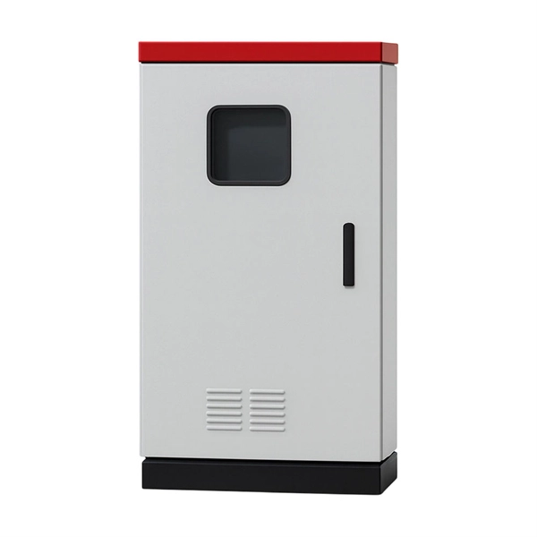
In this guide, we'll break down everything you need to know to install a distribution box correctly and confidently. Choose the right box based on environment (indoor/outdoor), load capacity, and durability. Check for proper IP/NEMA ratings and material quality. Ensure safe placement: install in. Whether you are an electrical contractor or a construction brigade, knowing how to properly and safely install distribution boxes is the basis of ensuring the safe operation of the entire system. This article details the process of installing them, which helps you comprehend distribution boxes. Electrical systems power our homes, offices, and industrial facilities, but behind every reliable electrical setup lies a crucial component that often goes unnoticed: the distribution box. This essential piece of equipment serves as the nerve center of your electrical system, managing power flow. Learn how to wire a distribution box step by step! This video shows real on-site footage of electrical installation, demonstrating safe and standardized wiring methods used by professionals. Just like travelers need clear pathways and safety protocols, your electrical circuits need proper management to prevent chaos.
[PDF]
In this video we are showing a complete Construction Site Electrical Distribution Panel setup. This includes MCCB, MCB, DB boxes, cable management, earthing and load distribution for machines. This. Through a real-world project scenario, we explore how structured connectors, IP67 plug systems, and modular distribution cabinets create safer, faster, and more reliable temporary electrical infrastructure. Temporary Power Should Never Mean Temporary Safety Construction sites rely heavily on. Insulation Tools: Ensure that wires and cables are properly insulated to prevent electric shocks. Training and education are key components of safe temporary electrical installations on construction sites. Workers need to be aware of the risks and know how to handle electrical equipment safely. Overhead Cables: Overhead supply from the supply point or metering point to the distribution boards on the site should be of a robust pattern. These regulations place a requirement on every employer to assess every work activity in order to identify any hazard that employees or any other person might encounter as a result of the work being carried out. HSE document INDG 163 gives advice on these regulations. The Provision and Use of work. If it's done poorly, you risk short circuits, fire hazards, or system failure. Done right, it ensures safety, compliance, and long-lasting performance. Choose the right box based on.
[PDF]
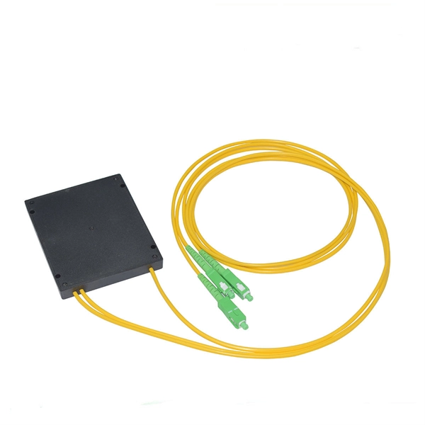
In this video, I walk you through my personal method of prepping and installing a 1:16 fiber optic splitter inside a sealed, weatherproof distribution box getting it ready for field deployment at a site. This is the way I've found to be clean, efficient, and reliable based on my experience in the. Optical splitters offer a cost-effective and dependable solution across various fiber optic applications. Also known as optical splitters, fiber splitters, or beam splitters, these devices are integrated waveguides ensuring wide bandwidth and minimal loss in high-frequency applications. They. How to install the splitter distribution box is the important information we need to know. This article includes the following: 1. Install the fixture 2. Ground the installation system 1. Have any questions? Talk with us directly using LiveChat. Fiber optic cable s transmit data using light signals, allowing for faster and more efficient data transfer compared to traditional copper cables. In the world of fiber optics, a crucial component for distributing signals is the fiber optic splitter box.
[PDF]
A novel approach to fibre Bragg grating spectra processing is proposed. The method is based on the use of nonlinear filtration and raising the spectrum value to the second power. A combination of geometric and arithmetic mean filtering is used as nonlinear filtration. The properties of the. A demodulation algorithm is vital for a fiber Bragg grating (FBG) sensing system. In this paper, a novel demodulation algorithm based on the variable-step-size method and cross-correlation algorithm is proposed to demodulate the wavelength of an FBG. By changing the step size of each calculation. Fiber Bragg gratings (FBGs) are widely used as sensors for temperature, strain, and vibration measurement. However, current FBG demodulation methods face issues with stability, size, and cost. In this study, we proposed a silicon-on-insulator (SOI) chip to demodulate FBGs based on random speckles.
[PDF]