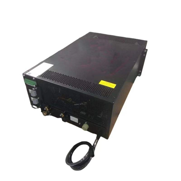
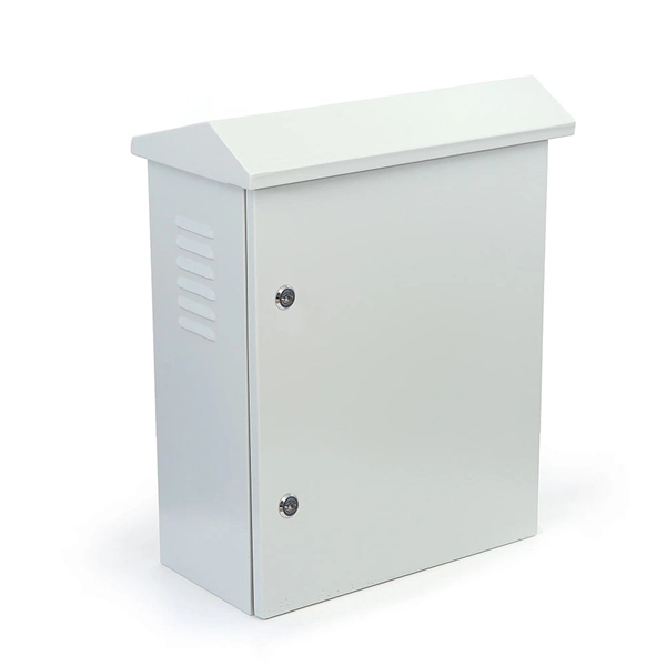
Grounding of the units: Attach a ground wire from one of the threaded studs (A) at the bottom of the housing, to the mounting plate (B). The ground resistance between. This section applies to grounding of transmission and distribution lines and equipment for the purpose of protecting employees. Note to paragraph (a): This section covers. Learn what OSHA requires for electrical grounding in general industry and construction, and what violations can cost you. OSHA's grounding requirements are spelled out primarily in two sets of regulations: 29 CFR 1910 Subpart S for general industry workplaces, and 29 CFR 1926 Subpart K for. Power from factory ground must be installed by a qualified electrician. Each DISTRIBUTION BOX and controller must be grounded. On the US market, a 5. 26 mm 2 (10 AWG) ground wire must be used, and in all other markets a 6 mm 2 must be used. The lockout/tagout procedure must consider several factors, one of which is grounding. Sometimes, installing temporary protective grounding is necessary. Whether you're a seasoned pro or just starting out, this comprehensive guide will give you practical.
[PDF]
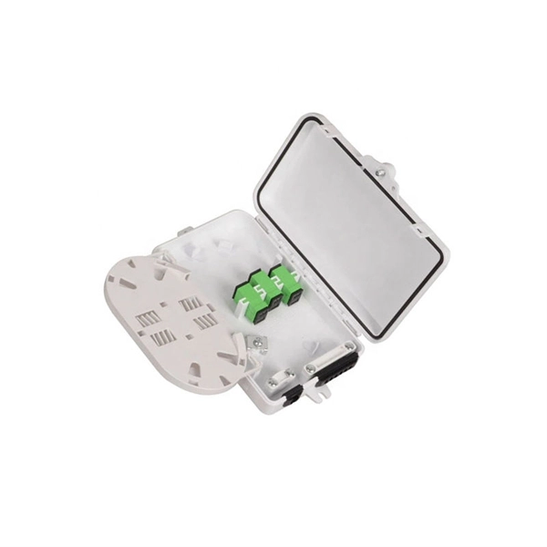
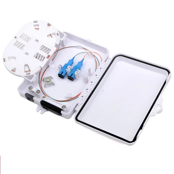
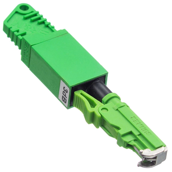
In this article, we will explore the different types of fiber optic pigtails, focusing on the distinctions between single-mode and multi-mode pigtails, and the unique applications for which each type is best suited. Executive Summary: A fiber optic pigtail is one of the most commonly specified yet least understood components in structured cabling. Get the wrong connector type, the wrong polish, or skip proper fusion splicing technique—and you're looking at elevated signal loss, increased back reflection, and a. In this guide, we'll break down what fiber optic pigtails are, how they work, their types, and how to choose the right one for your application. What Is a Fiber Optic Pigtail? A fiber optic pigtail is a short optical fiber cable that has a connector on one end and an exposed (unterminated) fiber on. A Fiber Optic Pigtail Complete Guide: As per types, connectors, and applications. In such contemporary fiber optic communication systems, low-loss, and connectivities, which have reliability, are crucial for not only maintaining high-speed but also high-quality data transmission. The most urgent. A fiber optic pigtail is a short length of optical fiber —typically 0. 5m to 2m—that has a factory-terminated connector on one end and bare fiber on the other end. The connector end is polished and tested under factory conditions, ensuring low insertion loss and high return loss.
[PDF]
Get the wrong connector type, the wrong polish, or skip proper fusion splicing technique—and you're looking at elevated signal loss, increased back reflection, and a field termination that fails certification. Executive Summary: A fiber optic pigtail is one of the most commonly specified yet least understood components in structured cabling. This article equips engineers and network operators with actionable strategies to diagnose. A fiber optic pigtail is a short length of optical fiber —typically 0. 5m to 2m—that has a factory-terminated connector on one end and bare fiber on the other end. The connector end is polished and tested under factory conditions, ensuring low insertion loss and high return loss. Avoiding common mistakes can save time, money, and network downtime. Dust or oil contamination leads to signal loss. Always clean fibers before splicing. Using the wrong connector (LC vs SC) can cause compatibility. Fiber pigtail failures can lead to unexpected signal loss, link instability, and repeated maintenance. Understanding how to identify early warning signs can help reduce downtime and protect your network from unnecessary failures. A visual check is often the first step when diagnosing a defective. However, when signal loss occurs in a 12 fiber pigtail, it can lead to disruptions in network performance, such as decreased data transfer speeds, increased error rates, or even complete outages.
[PDF]
Cable tray grounding wire is the safety connection that links your electrical system's cable tray to the ground. This provides a safe path for any stray electrical currents to flow safely into the earth, avoiding damage to your equipment and reducing the risk of electric shocks. There is no restriction as to where the cable tray system is installed. The metal in cable trays may be used as the EGC as per the limitations. Cable tray may be used as the Equipment Grounding Conductor (EGC) in any installation where qualified persons will service the installed cable tray system. Consider it as an emergency electricity exit. The main purpose of. Grounding in cable trays is an important practice to increase electrical safety and prevent hazards in case of faults. The methods and materials used may vary depending on the structure of the installation. However, the main principle should always be to ensure safe and effective grounding. It involves connecting cable trays to the facility's grounding system, providing a low-impedance path for fault currents and protecting personnel.
[PDF]
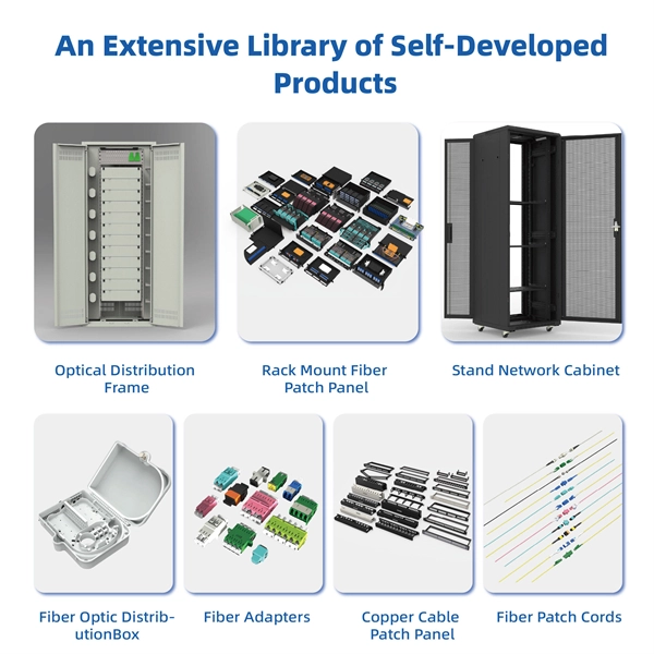
This guide covers everything: what fiber optic pigtails are, how they differ from patch cords, which connector and polish type to specify, how to choose between mechanical and fusion splicing, and the real-world applications where pigtails are the right call. Today, I'll show you how to pick the right patch cord or pigtail — step by step. A Fiber Patch cord connects two devices. You plug it into a switch, router, or patch panel. It's ready to use out of the box. A pigtail is for splicing. You fuse it to a. What Is a Fiber Optic Pigtail? A fiber optic pigtail is a short length of optical fiber —typically 0. 5m to 2m—that has a factory-terminated connector on one end and bare fiber on the other end. The connector end is polished and tested under factory conditions, ensuring low insertion loss and high. Fiber Optic Pigtail by Unisol is a high-performance, precision-engineered component designed to ensure seamless optical fiber termination across a wide range of network environments. While it may seem like a simple. Could I have 3” in of wiring coming in then pigtail another 3”? Or do I need to have 6” coming in regardless as one wire then anything pigtailed is extra? I want to have minimal wire in there to eliminate any potential shorts. I'm using a 20cu in plastic box with 2 runs of 12/2 coming in Context:.
[PDF]
Get the wrong connector type, the wrong polish, or skip proper fusion splicing technique—and you're looking at elevated signal loss, increased back reflection, and a field termination that fails certification. Once you nail the logic chain— raw fiber → protected cable → spliced pigtail interfaces → flexible patching —you control loss budgets, installation time, and maintenance risk. Key takeaway: Treat the four items like a relay team. Each runs a specific leg so your network hits performance targets. In the intricate ecosystem of fiber optic networks, two components play a critical role in ensuring seamless connectivity: patch cords and pigtails. While both are essential for linking fibers to devices or other cables, they serve distinct purposes and are designed for specific scenarios. Executive Summary: A fiber optic pigtail is one of the most commonly specified yet least understood components in structured cabling. Despite their widespread use and numerous advantages, there are some circumstances in which they might not be the ideal option. A fiber optic pigtail is very practical for on-site terminations where fusion or mechanical splicers are used. Preterminated connectors offer several advantages over. Today, I'll show you how to pick the right patch cord or pigtail — step by step. A Fiber Patch cord connects two devices. You plug it into a switch, router, or patch panel. It's ready to use out of the box. A pigtail is for splicing.
[PDF]
Use pigtails when connecting multiple wires to a single terminal, upgrading outlets or switches, or managing crowded electrical boxes. Pigtails play a crucial role in ensuring safe and efficient connections within electrical systems, especially when dealing with multiple wires or limited space. Understanding what a pigtail is and how it works can make your wiring projects smoother and safer. ” This method is especially useful when connecting wires to devices such as switches, outlets, and junction boxes, allowing. Proper using pigtails breaks this chain. By creating independent pathways, technicians isolate problems without shutting down complete circuits. Commercial buildings using this method report 83% faster troubleshooting times. The National Electrical Code mandates continuous neutral connections in. Optical fiber pigtails are short optical fibers used to connect fiber optics with other equipment (such as optical modules, splitters, etc. ), typically used in fiber optic networks. With advantages such as low insertion loss, high return loss, good interchangeability, and repeated plugging. A pigtail in electrical wiring is a short length of conductor used to transition from a bundle of multiple circuit wires to a single termination point, such as a device terminal or fixture connection. This technique is often employed when three or more wires need to be joined, ensuring that the.
[PDF]
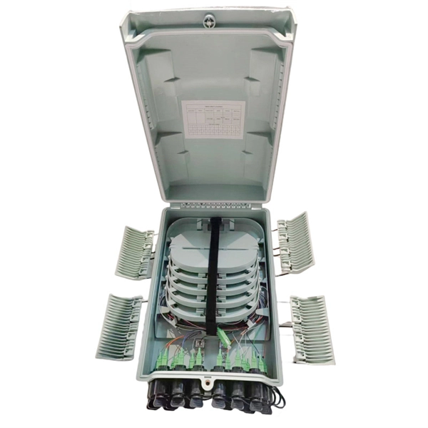
Fiber optic pigtails are short, single, or multi-strand pieces of optical fiber cables with a connector on one end and exposed fiber on the other end. They are typically used to terminate fiber optic cables and connect them to patch panels, equipment, or other termination points. This comprehensive guide aims to demystify fiber optic pigtails, exploring their design, functionality, and the myriad of applications they serve in today's technology-driven world. It is usually suitable for field termination using a mechanical or fusion splicer. Compared with quick termination or epoxy and polish connections placed on the field. Fiber pigtails are simple in appearance, yet essential in function. By combining factory-installed connectors with spliced bare fiber, pigtails ensure that network installers can create. Executive Summary: A fiber optic pigtail is one of the most commonly specified yet least understood components in structured cabling. Get the wrong connector type, the wrong polish, or skip proper fusion splicing technique—and you're looking at elevated signal loss, increased back reflection, and a. A key component in fiber optic systems is the fiber optic pigtail, a small yet indispensable part of the overall networking architecture. This unique design is the key to seamless integration with a variety of optical devices, ensuring signals traverse with.
[PDF]
Ungrounded: There is no intentional ground applied to the system-however it's grounded through natural capacitance. Reactance Grounded: Total system capacitance is cancelled by equal inductance. This decreases the current at the fault and limits voltage across the arc at the. In electrical engineering, a protective relay is a relay device designed to trip a circuit breaker when a fault is detected. : 4 The first protective relays were electromagnetic devices, relying on coils operating on moving parts to provide detection of abnormal operating conditions such as. To attain the desired reliability, the power system network is divided into two different protection zones. They are generator protection, transformer protection, bus protection, transmission line protection and feeder. Recognized under 2(f) and 12 (B) of UGC ACT 1956 (Affiliated to JNTUH, Hyderabad, Approved by AICTE - Accredited by NBA & NAAC – 'A' Grade - ISO 9001:2015 Certified) Maisammaguda, Dhulapally (Post Via. Kompally), Secunderabad – 500100, Telangana State, India To introduce all kinds of circuit. A protection relay is a crucial component of electrical systems that safeguard infrastructure, employees, and equipment from electric problems and malfunctions. It functions as a watchdog by constantly surveying multiple system components including voltage, current, frequency, and phase angle.
[PDF]
On the US market, a 5. 26 mm 2 (10 AWG) ground wire must be used, and in all other markets a 6 mm 2 must be used. Grounding of the units: Attach a ground wire from one of the threaded studs (A) at the bottom of the housing, to the mounting plate (B). Power from factory ground must be installed by a qualified electrician. Each DISTRIBUTION BOX and controller must be grounded. In the low-voltage three-phase four-wire neutral point directly grounded line, the construction unit should. Repeated grounding can be grounded directly from the neutral line or from the housing of the zeroing device. It looks like two lines, and in fact they are all together. The main functions of repeated grounding are as follows; (1) Reducing the ground voltage of the leakage device housing. In the. Today, we're diving deep into the world of distribution box grounding, breaking down the standards, and shining a light on those sneaky mistakes that even experienced electricians sometimes make. Good equipment grounding ensures personnel safety. Most North American distribution systems have a neutral that acts as a return conductor and as an equipment. This paper is intended to address how grounding system effectiveness affects each of these goals. Key Words - Grounding, Earthing, Safety, Surge Protec-tion, NESC, Neutral-to-Earth Voltage, Ground Currents, Stray Voltage. This paper is intended to give an overview of the vari-ous relationships.
[PDF]
NEC (National Electrical Code) Article 800 covers the general requirements for communications systems, including wiring methods, grounding, fire resistance, and installation practices for cables and equipment. The term “cable” means stranded conductor or a combination of conductors that includes Fiber Optic Supply Cable, Fiber Optic Communication Cable, or Non–Dielectric Fiber Optic Cable as defined in Rule 20. The term “messenger” is defined in Rule 22. The. This Applications Engineering Note (AE Note) discusses conventional bonding and grounding practices for conductive fiber optic cable and hardware installations within the scope of the National Electrical Code (NEC). This AE Note does not address outside plant fiber optic installations or. ned herein and with other Sections of this Specification as applicable to the completion of the installation. It applies to circuits that extend from the communications utility (such as telephone or. Article 800”General Requirements for Communications Systems covers general requirements for installing communications circuits, community antenna television and radio distribution systems, network-powered broadband communications systems, and premises-powered broadband communications systems. to n utral comm.
[PDF]