IEC 60255-1:2022 specifies common rules and requirements applicable to measuring relays and protection equipment, including any combination of equipment to form a distributed protection scheme for power system protection such as control, monitoring and process interface equipment . IEC 60255-1:2022 specifies common rules and requirements applicable to measuring relays and protection equipment, including any combination of equipment to form a distributed protection scheme for power system protection such as control, monitoring and process interface equipment . The IEC standard for protection relays plays a vital role in modern electrical power systems. Protection relays are essential devices used to detect abnormal conditions in electrical circuits. These conditions may include overloads, short circuits, or insulation failures. When such conditions are. The testing and verification of relay protection devices can be divided into four groups: Type tests are needed to prove that a protection relay meets the claimed specification and follows all relevant standards. Choose from interactive classroom training and hands-on. To meet this need, the IEC is currently working on the IEC 60255-1xx series of functional standards dedicated to protection relays and protection functions. Before looking at the benefits these standards can provide, let us review some background information.
[PDF]
Use a spectrometer, which measures the amount of visible light that is absorbed by a solution, to test the purity of copper. The copper can remain in its solid form during testing and the spectrometer will not contaminate the sample. Conducting a copper quality test helps ensure that the material meets the purity standards required for optimal function across these critical applications: Electrical Applications: Nothing matches copper's ability to conduct electricity efficiently. Minor contaminants can severely impact its. The purity of copper is measured by what percentage of copper is found in the substance. The purest copper is over 99. Each technique's critical detection limits, selectivity, complexity, and. This chapter comprehensively evaluates recent advances in analytical methods for detecting copper, including atomic spectrometry, molecular spectrophotometry, electrochemical sensors, voltammetry, and chromatography. Each method will be broken down into easy-to-follow steps, ensuring you gain the confidence to perform these tests yourself. Ready to dive in and. The Copper industry encompasses a vast range of applications, from pure grades like OFE (Oxygen-Free Electronic), OFC (Oxygen-Free Copper), and ETP (Electrolytic Tough Pitch) to high-alloy compositions such as Brass and Cupro-Nickel. The elemental analysis of Copper, whether for purity or alloy.
[PDF]

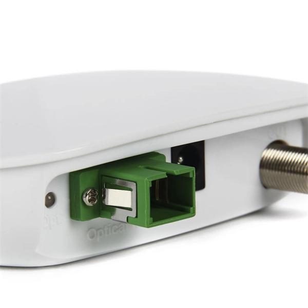
Discover the key differences between optical fiber cables and copper cables. OPTRAL analyzes the advantages and disadvantages to enhance connectivity. Optical and copper interconnection technologies represent two distinct approaches to data transmission, each with its own advantages and limitations. While fiber optics dominate in performance, copper retains its technical and economic justification. But how do you decide which one is best suited for your needs? This article delves into the technical comparison between copper and fiber optic cables. When it comes to modern data transmission, Fiber Optic cables and Copper Cables play pivotal roles in ensuring seamless connectivity. What Are Fiber Optic Cables? Fiber Optic cables function by transmitting data in the form of light pulses through optically pure glass fibers. These fibers are. “Fiber offers multiple technical advantages, including exceptional bandwidth, low attenuation and distortion over long distances, reduced bulk, as well as isolation from electromagnetic interference (EMI) and electrostatic discharge (ESD). ” Let's explore the characteristics, advantages, and. The two core material technologies used in almost all cables are fiber optic, and copper wiring. Whether you're looking at an HDMI cable, a USB cable, Ethernet patch cable, or any other kind of network of data transmission cabling, they are all built using copper or fiber optic internal wiring.
[PDF]
This article provides an in-depth exploration of OSFP copper cable technologies, including DAC, ACC, and AEC, with a focus on 400GB NDR splitter cable applications. Whether the signal is propagated by copper wire, optical fiber, Wi-Fi, or just yelling at the kids down the street, the signal is never as strong at the destination as it is at the source. In the case of physical voice communication, the kids will understand you if they are close-by. If they are. Insertion loss and attenuation are similar concepts, but one is assigned to a single component (insertion loss) whereas the other is assigned to generalized performance (attenuation). Both terms refer to a measurement comparing the signal strength received against a transmitted signal. Standard. Channel Master TV splitters are designed to equally divide the signals on the input port of the splitter to each of the output ports of the splitter. This. Insertion loss is the amount of energy that a signal loses as it travels along a cable link. It is a natural phenomenon that occurs for any type of transmission—whether it's electricity or data. This reduction of signal, also called attenuation, is directly related to the length of a cable—the. In fiber-optic networks like FTTx and PON, PLC splitters are key components for distributing optical signals to multiple users. However, each splitter has complex parameters, including insertion loss, return loss, polarization-dependent loss, and uniformity.
[PDF]
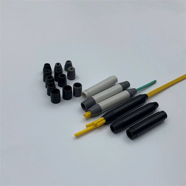
The key to choosing the appropriate one is to understand the theory on which each operates and the application that the attenuator will be applied to. Of course, you also need to be able to determine the attenuator value in decibels required for your application. Later in this article, we will discuss about the various advantages, disadvantages and application of attenuation. What is Attenuation? How Attenuation can be Prevented? What is Attenuation? Attenuation is a term in communication that refers to loss (reduction) in signal strength when a signal is. An optical attenuator, or fiber optic attenuator, is a device used to reduce the power level of an optical signal, either in free space or in an optical fiber. The basic types of optical attenuators are fixed, step-wise variable, and continuously variable. Optical attenuators are commonly used in. Fiber-optic attenuators are a specific type of optical attenuators which are used in fiber optics, e. for achieving a suitable signal level for a data receiver in a telecom system. Usually, such attenuators either have a housing equipped with some type of fiber connectors (e. The attenuator circuit will allow a known source of power to be reduced by a predetermined factor, which is usually expressed as decibels. Signal levels must be strong enough for data interpretation but not so strong as to damage the circuits in the receiver. Excessive fiber optic signal strength exceeding.
[PDF]