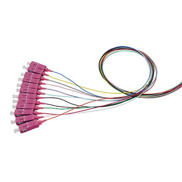
Mechanical splicing is a method of connecting two optical fibers without using heat or a fusion machine. Instead, it uses a small plastic or metal device to hold the fiber ends tightly together. A special index-matching gel is often used inside the splice to help light pass through the connection. You can manually splice the fiber patch cord with the help of the Procedure shown in the video. Now you can splice your patch cord. For network managers and technicians, a poor splice can lead to significant signal degradation, network downtime, and costly troubleshooting. At Turn-Key. This wikiHow article teaches the process of manually splicing patch cords and fusion splicing two fiber optic strands together in an 11-step process. The video also demonstrates how to fix a cut or. Fiber cable splicing is a critical step in building reliable fiber optic networks. Whether in data centers, telecom rooms, or outdoor FTTx deployments, proper splicing inside a fiber enclosure ensures low signal loss, long-term stability, and easy maintenance. This guide explains what fiber cable. In this guide, we cover the basics of fiber optic splicing, how to perform splicing using two different methods, and finally some best practices to perform good fiber splicing. What is Fiber Optic Splicing and Why is it Needed? – #1. Use and Maintain Your.
[PDF]
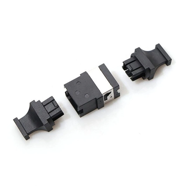
A ferrule puller tool is a specially engineered hand tool designed to extract ferrules from tubing, pipe fittings, and compression joints. The CK01, CK03, and CK05 Fiber Optic Termination / Connectorization Kits include all the necessary tools and supplies to install connectors on single mode and multimode optical fiber. All that's needed to create a fiber optic patch cable is the optical fiber and appropriate connectors. Our termination kits, for example, are equipped with all of the necessary tools — pin and socket polishing tools, jacket strippers. post polishing failures. The document is intended to inform and educate about polishing processes and commercial automated polishing equipment with various fixturing in order to achieve a stable low insertion loss, targeted return loss, acceptable 3D endface geometry, and defect free visual fiber. The ratchet in these crimpers applies the right amount of pressure to ensure a complete crimp in wire ferrules every time. Fixed Crimping Slot— Crimpers with a fixed crimping slot have separate slots for each wire gauge. Read more: How Do I Know Which Crimping Tool To Use? What are Cable Ferrule Crimping Tools? Cable ferrule crimping tools are tools or machines. The Stainless Burner has two ceramic combustion tubes, which require periodic replacement: an inner and an outer tube. Tools • 1 - 1/4” Open End Wrench • 1 - 3/8” Open End Wrench • 2 - 7/16” Open End.
[PDF]
There are currently three methods of looking inside a fiber optic connector: (1) Non-destructive X-ray (2) Lossless sonar (3) Destructive cross section These methods help engineers determine the causes and effects of fiber optic connector failures and monitor the connector assembly. There are currently three methods of looking inside a fiber optic connector: (1) Non-destructive X-ray (2) Lossless sonar (3) Destructive cross section These methods help engineers determine the causes and effects of fiber optic connector failures and monitor the connector assembly. Fiber Optic Center offers a unique cross-sectioning service to identify and isolate problems related to fiber optic terminations that would otherwise be invisible. All. There are two major uses for visual inspection of fiber optic connectors. Video microscopes should have ability to record images and some may have ability to analyze connector condition to standards. Look for dirt, contamination, scratches or any other problem. Since connectors are susceptible to damage that is not immediately obvious to the naked eye—the inspection phase is vital. When proceeding with the inspection of connectors, there are two main components to inspect: the connector itself and the ferrule. With the press of a single button, FOCIS Flex auto-focuses, captures and centers the end-face image, applies Pass/Fail rules, displays image and Pass/Fail results, saves results internally and/or wirelessly transfers data to a.
[PDF]
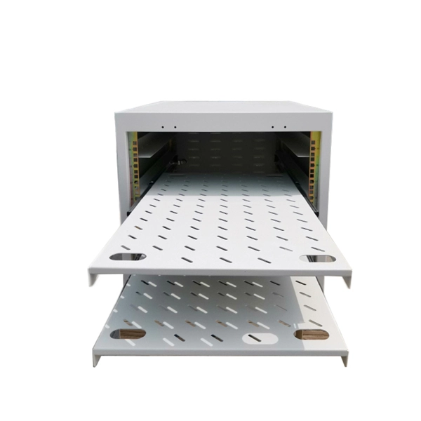
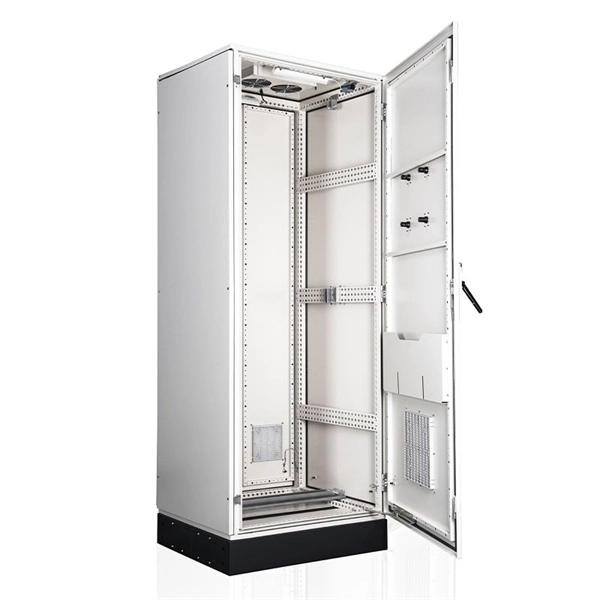
In this guide, we'll break down everything you need to know to install a distribution box correctly and confidently. Choose the right box based on environment (indoor/outdoor), load capacity, and durability. Check for proper IP/NEMA ratings and material quality. Ensure safe placement: install in. The National Electrical Code (NEC) requirements might seem like bureaucratic red tape, but they're more like the safety rails that keep everything running smoothly and prevent dangerous surprises. "Getting your distribution box installation right isn't just about passing inspection - it's about. This Instruction provides guidance and requirements for the approval and installation of wire line and optical fiber distribution systems used to protect unencrypted, National security information (NSI) through areas of lesser classification or control. You'll learn what they are, why they're required, the difference. In modern electrical systems, cable distribution boxes (also known as electrical distribution boxes or distribution boxes) play a crucial role as the key hub for managing, distributing, and protecting circuits. Whether it is residential buildings, commercial facilities or industrial sites, the. Verify the specifications of the power distribution box against project requirements. Ensure all components are present and undamaged. Confirm compliance with local codes and regulations. Select an appropriate installation location with adequate space.
[PDF]
The scope of this document provides clarification on the inspection requirements to undertake full inspection on Low Voltage (LV) distribution boards, Pillars and Transformer take off cabinets under Live conditions. LV distribution boards, pillars and. This section covers the operation and maintenance of electric power generation, control, transformation, transmission, and distribution lines and equipment. These provisions apply to: Power generation, transmission, and distribution installations, including related equipment for the purpose of. This manual provides guidance and instruction about the requirements of the G. 165 Program to perform and document patrols and inspections. This manual also provides guidance about how to assess and document field conditions that meet the criteria for a compelling abnormal condition, per Job Aid. Check for signs of corrosion or rust. Inspect for any physical damage to the enclosure. Ensure that all labels and warning signs are legible. Verify that the box is securely mounted and that there are no loose connections. You must make safety your top priority when working with low voltage distribution boxes. LV distribution boards, pillars and cabinets comprise of three main components: The. 1). LV Intrusive Switchboard Low-voltage intrusive switchboards regulate and distribute power in buildings and facilities. Power distribution & circuit protection depend on it. Multiple circuit.
[PDF]