If an optical module is installed in a running router, you can run the display transceiver command to view parameters of the optical module, including the center wavelength, transmission distance, fiber types supported, receive optical power, and transmit optical power. Some users may be ambivalent about the measurement of an optical module's transmission distance in practice. If you are one of them, find out the methods in this article now! 1. Working Wavelength 3. Compliant Protocols & Standards 5. An SFP (Small Form-factor Pluggable) module transmits data over fiber using specific wavelengths and power levels, which directly influence how far the signal can travel before degradation occurs. Unchecked optical modules can cause: Testing ensures compliance with IEEE 802. 3 and MSA. An OTDR (Optical Time Domain Reflectometer) is a measuring instrument intended to measure the transmission loss and distance of optical fibers, locate cable cuts, and evaluate the connection loss and reflectance (return loss) of fusion splices, mechanical splices, connector connections, etc. These fibers are most commonly made of glass and are very thin, typically less than a tenth of the width of a human hair. Fiber optic cable.
[PDF]
The optical budget refers to the maximum allowable signal loss between the transmitter and receiver in a fiber-optic link. It ensures that the received signal is strong enough for the equipment to process data without errors. Calculated in decibels (dB), it is the difference between the. After measuring the loss of a fiber link, you now have to determine if that fiber link loss is acceptable or not. You can either compare this loss value to the application requirement or calculate the expected loss based on how many connectors and splices are in the link along with the length of. Optical module channel loss resistance refers to the maximum optical path attenuation that an optical transceiver module can tolerate while still maintaining compliant signal integrity, error performance, and link stability. There are many reasons for optical fiber loss, such as optical fiber material's absorption/scattering of light energy, bending.
[PDF]
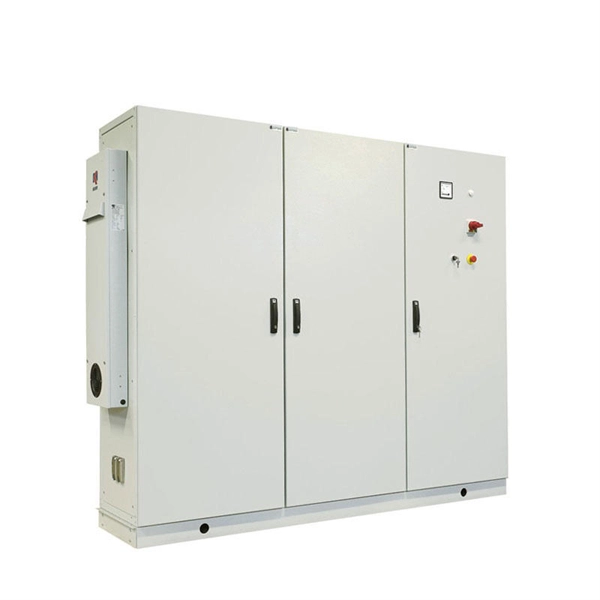
These modules typically consist of a laser or LED transmitter, a photodiode receiver, and supporting electronics. Optical modules are compact devices that convert electrical signals into optical signals and vice versa. They are used in fiber optic communication systems to transmit data over long distances with minimal loss and interference. The Cisco NCS 2000 Series encompasses platforms from Cisco NCS 2002 onwards. In intelligent computing centers built around large-scale GPU clusters, network bandwidth, latency, and reliability directly determine the efficiency of AI training, big data processing, and other tasks. As a core component connecting servers, switches, and storage systems, optical modules play a. What is an SFP? SFP (Small Form-factor Pluggable) is a compact, hot-pluggable network interface module used to connect network devices (switches, routers, firewalls) to fiber optic or copper cables. The OLT is installed at the headend and each OLT port connected into the fiber to the designated service area and the splitters installed to serve the intended users. Operating at the physical layer of the OSI model, optical modules are core devices in optical.
[PDF]
🔍 What Is a 400G Optical Module? A 400G optical module performs photoelectric conversion: With a 400 Gbps transmission rate, these modules support industry evolution from 100M → 1G → 25G → 40G → 100G → 400G → 1T. They form the backbone of high-throughput data center networks and AI. PAM4 (4-Level Pulse Amplitude Modulation): This is the predominant modulation technique used in 400G modules. PAM4 allows each symbol to represent two bits of information, effectively doubling the data rate compared to traditional NRZ (Non-Return-to-Zero) modulation 1. Multi-Mode Fiber (MMF):. 400G is optical networking technology that can transfer data at speeds of up to 400 gigabits per second on a single optical wavelength. It provides high-capacity bandwidth to support data-hungry use cases such as data centre interconnects, AI, 5G and IoT. The terms 400G, 400Gbps and 400GE/400Gbe. 400G QSFP-DD optical transceivers come in various flavors: SR8, DR4, FR4, LR4, and more. QSFP-DD DR4 has a key advantage in that it can interoperate with 100G single lambda optics. 3bs Clause 124 defines a DR4 transmitting a 400Gb/s aggregated signal on 4 fibers (PSM4). It converts electrical signals into optical signals and vice versa, enabling data transmission over optical fibers. Choosing between 400G and 800G optical modules depends on your workloads, scale, and budget.
[PDF]
This step-by-step guide aims to provide a comprehensive understanding of the techniques and considerations involved in successfully connecting optical fibers, offering invaluable insights for professionals and enthusiasts in the field. In high-speed data networks, the seamless integration of fiber optic cables with SFP (Small Form-Factor Pluggable) modules is critical for reliable signal transmission. SFP transceivers bridge electrical and optical signals, making them indispensable in data centers, telecom networks, and. Proper connection of fiber optic cables is essential to harness these benefits fully, as even minor errors can lead to significant performance issues like signal loss. This article will guide you through the necessary tools, materials, and methods on how to connect fiber optic cables effectively. This section describes how to install optical transceivers on the SFP or SFP+ ports and connect them to the ports of the peer device using optical fibers according to the network plan. The USG supports both 1 Gbit/s, 10 Gbit/s, and 40 Gbit/s optical modules. The optical modules at both ends are. There are many types of fiber optic connectors, including SC, LC, FC, ST, D4, MU, MT/MPO, etc. These connectors can be divided into single-mode and multi-mode fiber optic connectors according to their structure and purpose. In this tutorial.
[PDF]
Optical modules are compact devices that convert electrical signals into optical signals and vice versa. They are used in fiber optic communication systems to transmit data over long distances with minimal loss and interference. Operating at the physical layer of the OSI model, optical modules are core devices in optical. An optical module is a typically hot-pluggable optical transceiver used in high-bandwidth data communications applications. Optical modules typically have an electrical interface on the side that connects to the inside of the system and an optical interface on the side that connects to the outside. The Transmitter Optical Sub Assembly (TOSA) is responsible for the emission of light. This assembly comprises a light source, such as a laser diode or a semiconductor light-emitting diode (LED), an optical interface, a. Optical modules are essential components in modern communication networks, enabling high-speed data transmission over fiber optic cables. As the demand for faster and more reliable internet and data services grows, understanding these devices becomes increasingly important. Among various optical module form factors, SFP (Small Form-Factor Pluggable). SCALE CPO solution is the industry's first OCI MSA capable platform and built with GF's proven silicon photonics technology MALTA, N., May 4, 2026 – GlobalFoundries (Nasdaq: GFS) (GF) today announced the introduction of its SCALE™ optical module solution for co-packaged optics (CPO).
[PDF]
An optical module is a typically hot-pluggable optical transceiver used in high-bandwidth data communications applications. Optical modules typically have an electrical interface on the side that connects to the inside of the system and an optical interface on the side that connects to the outside world through a fiber optic cable. The form factor and electrical interface are often specified by an int. Electrical Interface TypesThere have been multiple variants of the electrical interface of optical modules that have been used over the years. The earliest forms of optical modules had an analog electrical interface. In the transmit dir. Many different forms of optical modulation and multiplexing have been employed in optical modules. The most common modulation technique historically has been or NRZ.
[PDF]
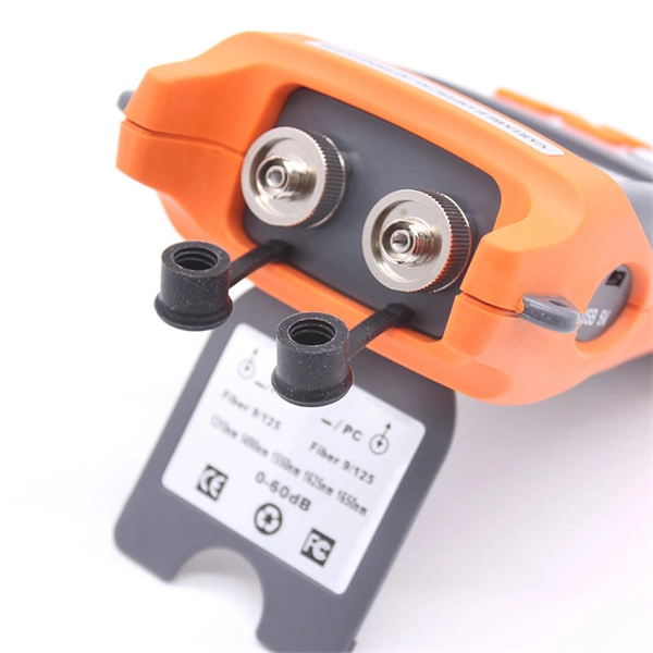
A common test setup to evaluate Stressed Receiver Sensitivity involves measuring the Optical Modulation Amplitude (OMA) using a square wave, per the standard guidelines. Receiver sensitivity stands as a critical parameter impacting an optical transceiver's functionality. It denotes a module's capability to function in challenging environments and aids network operators in determining the system's maximum reach or link margin. These metrics provide insights into how well your transceivers perform under different conditions, ensuring seamless data transmission. Optical. Whether you're a network engineer validating new inventory or an integrator preparing for deployment, knowing how to test optical transceiver modules can save time, reduce failures, and ensure SLA compliance. Unchecked optical modules can cause: Testing ensures compliance with IEEE 802. 3 and MSA. In optical communication systems, sensitivity is a measure of how weak an input signal can get before the bit-error ratio (BER) exceeds some specified number. The standards body governing the application sets this specified BER. For example, SONET specifies that the BER must be 10 -10 or better. Why Fiber Optic Transceiver Testing is Important? Identify faults and failures: Transceiver testing helps in identifying any faults.
[PDF]

The TE100-MGBFX is compatible with Duplex-LC fiber connector types and supports fiber optic connection distances of up to 2 kilometers (1. Long distance fiber networking for industrial, manufacturing, and corporate/education campus applications. Learn why IT Pros trust StarTech. com for performance connectivity accessories. TESTED FOR COMPATIBILITY: Hot-swappable in MSA Compliant routers and switches; DDM support reports the transceiver's status to most SNMP network management tools. The MFB-FX by Planet Technology is an 100Mbps Fast Ethernet SFP Fiber Transceiver. Distance: 2km PLANET's 100Mbps Fast Ethernet SFP Fiber Transceiver utilizes a wavelength of (1310nm) FP LD, which enables a data transmission of up to 2km on a multimode optical fiber and up to 60km on a single. Designed for short fibre optic distances: Supports multimode connections with a range of up to 2 km – ideal for data centres and internal networks. 100 Mb/s data rate for FX applications:. The 100BaseFX MM SFP 2km is a multimode fiber SFP (mini-GBIC) transceiver. Featuring an LC style connector, it supports 100BaseFX Ethernet over multimode fiber for distances up to 2 kilometers, providing a reliable fiber optic connection. When to Choose Single-mode? For distances exceeding 2 kilometers or for applications.
[PDF]
In the field of optical communication, the packaging of optical devices plays a crucial role in the performance and application of optical modules. Common optical device packaging methods include COB (chip-on-board packaging), BOX and coaxial packaging. Today, we will discuss the differences. This article analyzes the requirements of optical transceivers and discusses packaging methods and optical chip types to help readers better understand their design and manufacturing process. They are used in telecom and data communication applications and can be packaged in different ways, including TO, Box, and COB packaging. Regardless of the type of optical module, the. COB packaging means chip-on-board packaging, and the laser chip is adhered to the PCB substrate, which can achieve miniaturization, light weight, high reliability and low cost. The traditional single-channel 10Gb / s or 25Gb / s rate optical module uses SFP package to solder the electrical chip and. The optical transceiver module has three major components, which are opto-electronic devices (TOSA/ROSA), a circuit board with electronic components (PCBA) and optical interfaces (housings) such as LC, SC and MPO. Figure1: Components of an Optical Transceiver The optical transmitting part is.
[PDF]
Optical trap or "tweezers" is a device used to apply piconewton sized forces and make precise measurements on a scale of roughly one micron. It can be created by applying a precisely focused laser onto a dielectric material. Thorlabs' OTKB (/M) Modular Optical Tweezers provide users with a tool for trapping and manipulating microscopic-sized objects. These laser-based tweezers, or traps, have been employed in numerous biological experiments. Biological applications for optical tweezers include trapping viruses and. Our advanced optical trap generator based on ultra-fast AOD technology. Versatile and flexible optical trap manipulation designed for biological samples. Learn to calibrate the 20. Use calibration information to observe the rotation of E. coli bacteria, and determine the forces required to stop this rotation. Based on their design, Thorlabs has collaborated with the aforementioned authors to design an OTKB optical trapping kit that includes all necessary components and provides the same capabilities. Enclosed into a high-quality aluminum box and assembled onto the. Torr Scientific offers a range of magneto-optical traps (MOT) (also known as atom trap chambers) used as part of ultra-cold vacuum systems, to capture atoms for testing purposes. This is a chamber module, formed of low-magnetic permeability materials for use at ultra-low temperatures nearing.
[PDF]
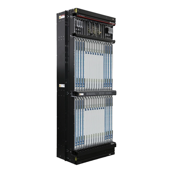
CFP is a new optical module standard that can be used in data communication and telecommunications fields. QSFP28: with the same interface size as a QSFP+ module. An optical module is a component that completes electrical/optical conversion on an optical network. Connector Figure 3-199 shows an SFP/eSFP optical module. Figure. The Combo interface, also known as the optical-electrical multiplexing interface, consists of two Ethernet ports (one optical and one electrical) on the device panel, and there is only one forwarding interface inside the device. The Combo electrical port and its corresponding optical port are. Intended Audience OptiX OSN 3500 System Description is intended for any one who needs a general command of the features, applications, structure and technical specifications of the OptiX OSN 3500. Page 9 About This Manual OptiX OSN 3500 TM - SD Conventions The following conventions are used. This article summarizes several solutions for using optical modules with switches and common problems encountered during usage, along with specific solutions. Huawei S5720-32P-EI-AC Switch II. How to Configure Optical Ports on Huawei S5720-32P-EI-AC Switch? Problem: All optical ports cannot be. The SFP-FE-SX-MM1310 (part number: 02315233) is a Huawei-certified 100M optical module. However, the Vendor Name field displays the original manufacturer name, instead of HUAWEI.
[PDF]
The SFP optical module is a standardized, modular assembly designed to be quickly installed or removed from a device's port without requiring the device to be powered down. This key feature—being hot-pluggable —is essential for simplifying network maintenance and minimizing downtime. SFP (Small Form-factor Pluggable) is a compact, hot-pluggable network interface module used to connect network devices (switches, routers, firewalls) to fiber optic or copper cables. It converts electrical signals into optical (or copper) signals and vice versa. An SFP transceiver acts as a compact, hot-swappable optical transceiver that. An SFP switch uses Small Form-Factor Pluggable (SFP) modules to form a network switch for high-speed connectivity between devices. These interchangeable modules support various media types, including copper or fiber-optic cables, providing flexible networking options based on specific requirements.
[PDF]
SFP28 (Small Form-Factor Pluggable 28) is an enhanced version of SFP+, designed to support 25Gb/s data rate transmission while maintaining the same package type. SFP28 is backward compatible with SFP+. However, compatibility can vary based on the specific SFP models, networking equipment, and vendors involved. It's advisable to consult your vendor for precise information regarding compatibility. ①. This article helps network engineers and field techs confirm SFP backward compatibility when mixing SFP, SFP+, and SFP28 optics in the same switching ecosystem. You will get concrete specs, a decision checklist, and troubleshooting patterns that show up in daily operations. ① Plug a 1000BASE-SX SFP transceiver into the SFP port on a gigabit. Common form factors are SFP (1 G), SFP+ (10 G), SFP28 (25 G), QSFP+ (40 G) and QSFP28 (100 G). The question we answer below is simple: “Which of these can I mix and match without killing the link? What “compatibility” really means? All reputable transceivers follow the Multi-Source Agreement (MSA). SFP28 optical transceiver modules provide a transmission rate of 25 Gbps and use LC connectors. 25G SR/eSR are not supported for use. Q: Can I use an SFP transceiver in SFP28 ports? A: Yes, you can. However, it's important to note that while SFP transceivers and cables can be plugged into SFP28 ports, they won't support the higher 25Gb/s data rate of the SFP28.
[PDF]
An optical module is a typically hot-pluggable optical transceiver used in high-bandwidth data communications applications. Optical modules typically have an electrical interface on the side that connects to the inside of the system and an optical interface on the side that connects to the outside world through a fiber optic cable. The form factor and electrical interface are often specified by an int. Electrical Interface TypesThere have been multiple variants of the electrical interface of optical modules that have been used over the years. The earliest forms of optical modules had an analog electrical interface. In the transmit dir. Many different forms of optical modulation and multiplexing have been employed in optical modules. The most common modulation technique historically has been or NRZ. Optical modules have a series of components inside, some of which have received attention from standards development organizations. In many cases, the baud rate of the optical interface do.
[PDF]