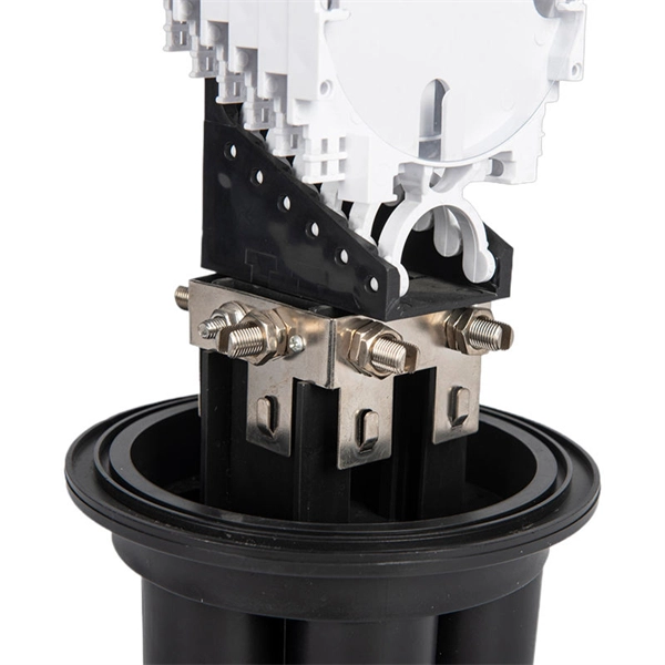
This guide will walk you through everything you need to know to install a plenum kit — from tools and prep to sealing and insulation — so you can boost efficiency, comfort, and airflow in your home. 📦 What Comes in a Plenum Kit? A plenum kit is essentially a pre-fabricated air. Before beginning installation, turn off the circuit breaker for the area you are working in. Confirm power is off with a voltage tester. Make sure the junction box has been properly installed and "rough-wired" all wires should be run through the box and secured before installing BOX SHELL. Fold /. Your Queries:-how tohow to insulate around electrical boxes,electricalelectrical boxelectrical boxesair sealed electrical boxinsulating around electrical box. Foam gaskets fit around the box and behind the cover plate, while putty pads adhere directly to the back of the cover plate. Both options will prevent drafts and improve energy efficiency. It only involves adding the foam insulation material in all areas you deem necessary and then sealing any air gaps you could find around the box. There are 3 common methods for it. This involves applying a fire-rated sealant, specifically a caulk or minimal-expanding foam, to the small gap where the box meets the surrounding drywall. Choose the right box based on environment (indoor/outdoor), load capacity, and durability. Ensure safe placement: install in.
[PDF]
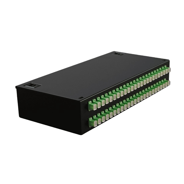
To check a fiber connection, connect a jumper to the optical source port and the other end to an optical meter. Press the “test” or “signal” button to send a signal from the source to the meter. In this blog, we'll explore different methods, including using a flashlight, advanced tools like Fluke testers, and more cost-effective options for testing fiber optics. First, we'll show you the. This guide will walk you through diagnosing and resolving common fiber network issues efficiently. Why Do Fiber Networks Fail? Despite their robustness, fiber networks can fail due to: Physical Damage : Cuts, bends, or contamination in fiber cables or connectors. Below is an in-depth guide on how to assess the health and performance of a fiber optic connection: Before relying on technical tools, start. While there are many different fiber optic cable tests, the most common version is an insertion loss test, also known as an attenuation, jumper, or connectivity test. This test requires a special testing kit and protective eyewear, but it will help you diagnose problems with the cable's. We'll explain why it's vital to test fiber optic cables, the three most popular methods, and when you should use them. Related: Fiber Optic Connectors – Identification Guide Regularly testing fiber optic cables helps minimize network downtime, lengthens the network's longevity, reduces maintenance.
[PDF]
A spectrophotometer is a piece of spectroscopy equipment measures the amount of light absorbed by a sample. This measurement can be useful in many research applications: To identify materials by mapping molecular absorption profiles. To work out solute concentrations in solutions. Specifically, a UV-Visible Spectrometer measures the absorption or transmission of light in the ultraviolet (UV) and visible (Vis) regions of the electromagnetic. A spectrometer is a scientific instrument that analyzes light to reveal information about materials. It functions by separating light into its constituent wavelengths, much like a prism splits sunlight into a rainbow. This analytical capability makes spectrometers valuable tools across many fields. Spectrophotometry is an experimental technique that is used to measure the concentration of solutes in a specific solution by calculating the amount of light absorbed by those solutes. It is widely used in laboratories to analyze various substances, from liquids to gases. Here's a step-by-step guide on how to use a spectrophotometer. When you use spectrophotometry, you gain skills that help in many science fields. This guide makes spectroscopy simple by showing you how to use teaching tools and real experiments. The basic principle is that each compound absorbs or transmits light over a certain range of wavelength. This measurement can.
[PDF]
An OTDR is a powerful tool that helps technicians and engineers assess the health of fiber optic cables. OTDRs inject high-powered light pulses into the fiber using specialized laser diodes. As these light pul.
[PDF]
Using a multimeter, check continuity between the black connector and the marked pin of the optocoupler input that is not working. If there is no continuity, the possible causes are: Connect a 5 V to 24 V signal to the input being tested. Measure the voltage at the marked. Using a multimeter, you can perform several tests to assess the functionality of an optocoupler. Each test targets a specific aspect of the optocoupler's operation. An optocoupler is an essential electronic component that transfers signals without a direct electrical connection. more n this video, you will learn how to test an optocoupler (optoisolator) using a. Optocoupler is one type of ICs, It isolates input and output section by using optical technology this feature increase safety of circuit. Optocoupler has many part number, different part number has different output type so before checking it has to use part number to research with datasheet and. If any optically isolated input on the controller is not working, follow the steps below to identify the cause. For our demo purposes, we will be using the PC817, a commonly used transistor output optocoupler in electronics. An opto-isolator contains a source (emitter) of light, almost always a near infrared light-emitting diode (LED), that converts electrical input signal into light, a closed optical channel (also called dielectrical channel, and a photo sensor, which detects incoming light and either generates.
[PDF]
Explore our full range of inspection tools, OTDRs, power meters, FTTx diagnostics, and software designed for fast, reliable network deployment and maintenance. Pocket-sized and performance packed, AFL optical time domain reflectometers (OTDRs) and fault locators certify new fiber installations and locate faults in deployed fiber optic networks. Easy operation makes even a novice a testing expert. Robust Cloud- and PC-based reporting tools that provide. Do you also provide customisation in the market study? Yes, we provide customisation as per your requirements. To learn more, feel free to contact us on sales@6wresearch. com Any Query? Click Here. A Two-Way Optical Loss Tester (OLTS) that's perfect for medium to ultra high fiber count loss, length and optical return loss testing applications on multimode fiber at 850 / 1330nm. A pair of these compact instruments set new standards of productivity, accuracy and ease of use. A multimode APC. O/E LAND, a provider of optical measurement, switching, and infrared photonic instruments, is featured on GoPhotonics for its diverse portfolio of optical spectrum analyzers, fiber optic switches, circulators, detectors, and power meters designed for advanced photonic and sensing systems. Used together with GAO's C0220003 handheld optical light source, it offers a quick and accurate testing solution for both single and multi-mode fibers. The VIAVI OMK-3xV2 optical test kits are a range of pocket-sized and rugged instruments for installi.
[PDF]
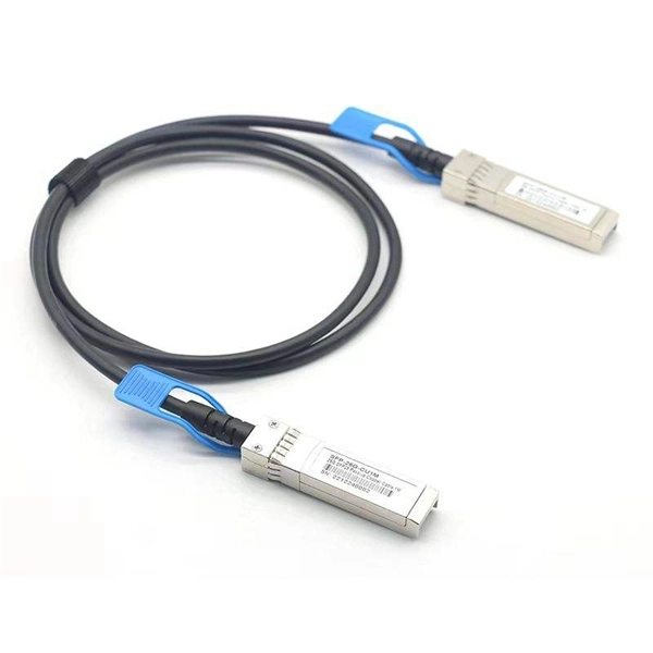
A common test setup to evaluate Stressed Receiver Sensitivity involves measuring the Optical Modulation Amplitude (OMA) using a square wave, per the standard guidelines. Receiver sensitivity stands as a critical parameter impacting an optical transceiver's functionality. It denotes a module's capability to function in challenging environments and aids network operators in determining the system's maximum reach or link margin. These metrics provide insights into how well your transceivers perform under different conditions, ensuring seamless data transmission. Optical. Whether you're a network engineer validating new inventory or an integrator preparing for deployment, knowing how to test optical transceiver modules can save time, reduce failures, and ensure SLA compliance. Unchecked optical modules can cause: Testing ensures compliance with IEEE 802. 3 and MSA. In optical communication systems, sensitivity is a measure of how weak an input signal can get before the bit-error ratio (BER) exceeds some specified number. The standards body governing the application sets this specified BER. For example, SONET specifies that the BER must be 10 -10 or better. Why Fiber Optic Transceiver Testing is Important? Identify faults and failures: Transceiver testing helps in identifying any faults.
[PDF]
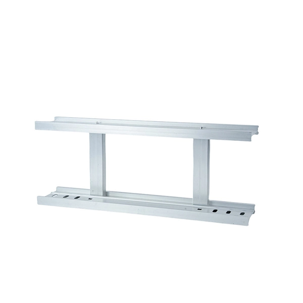
Fiberglass trays are the least effective at dealing with heat. Fiberglass cable tray loses 10% of its rated strength at temperatures as low as 100°F. Eaton's B-Line series fiberglass cable tray systems provide an economical support system with superior strength at room temperatures and dependable load bearing capabilities at continuously elevated temperatures. While fiberglass cable tray systems utilize a heat-cured resin that doesn't melt at. Choosing fiberglass cable trays for elevated-temperature environments requires moving beyond supplier claims. Your assurance as an engineer should be based on evidence, specifically the Air Thermal Aging Test Report. You don't need to be a materials expert. You need to know how to evaluate three. Our trays are manufactured from Fiberglass Reinforced Plastic (FRP) using high-grade resins to ensure outstanding corrosion resistance, mechanical strength, and electrical insulation. FRP Cable Trays are a superior alternative to conventional steel or aluminum trays, particularly in aggressive. Fiberglass Ultra-Sleeve High-Temperature Sleeving is a protective sleeve that is ideal for those areas where your cable runs through a particularly harsh environment of flash heat or flame, chemical or mechanical abuse.
[PDF]
Move and Change Shape: Ground shaking from an earthquake can make cable trays move and bend. This affects how stable they are and how much weight they can hold. This damages the whole cable tray. Cable tray and conduit systems have consistently performed well at conventional power and industrial facilities subjected to past strong-motion earthquakes larger than eastern U. plant safe shutdown earthquakes (1). This is so even though the systems are typically not designed for earthquake. The Pacific Earthquake Engineering Research (PEER) Centre has been developing a performance-based earthquake engineering (PBEE) methodology, which is based on explicit determination of performance, e., monetary losses, in a probabilistic manner where uncertainties in earthquake ground mo-tion. This appendix provides the design criteria for seismic Category I cable trays and their supports. Seismic Category II cable trays and their supports are also designed utilizing the design criteria of this appendix. They may be supported singly or there may be several pieces of onduit or buss ducts attached to a common trapeze. On some occasions the condui hanger rods 12 in or less in length be restrained. The 12 in length was determined based on the natural.
[PDF]