Industry standards such as the NEC (National Electrical Code) Article 770 and NFPA 70 provide binding requirements, while standards from IEEE and TIA offer additional guidance. When a fiber optic cable contains any of the following metallic elements, each must be bonded and grounded according to. NEC 2026 Article 750 consolidates grounding and bonding requirements for all limited-energy systems. Learn what changed, proper bonding methods, IBT requirements, and common mistakes to avoid. Grounding and bonding requirements for fire alarm, security, communications, and other limited-energy. This recommended practices document is a comprehensive manual for optical fiber construction and testing. Here are some highlights from Part IV of Article 770. The Code Making Panels (CMPs), composed of volunteers with full-time jobs, struggle to standardize and clarify terminology. Part I of Art. Although these are not current-carrying conductors, how and where you install them can affect “the practical safeguarding of persons and property from hazards arising from the use of. Understanding NEC Article 770 is the key to ensuring that optical fiber cables and raceways are installed safely, legally, and efficiently. This section of the National Electrical Code specifically addresses the unique characteristics and hazards associated with transmitting light for control.
[PDF]
Grounding in cable trays allows electrical leakage from the outer surfaces of the conductors to be channeled into the tray. It helps to safely direct dangerous currents that may result from electrical faults to the ground. Cable tray may be used as the Equipment Grounding Conductor (EGC) in any installation where qualified persons will service the installed cable tray system. There is no restriction as to where the cable tray system is installed. The metal in cable trays may be used as the EGC as per the limitations. Enhanced safety: Grounding provides a safe path for fault currents to flow, significantly reducing the risk of electric shock to personnel and preventing damage to equipment due to overvoltage or insulation failure. It also safeguards against fire hazards caused by excessive heat generated during. that system to lose its UL Classification. If you take what UL states literally, ANY cut to tray (ladder or wi e) would cause a loss of UL Classification. The methods and materials used may vary depending on the structure of the installation. However, the main principle should always be to ensure safe and effective grounding. These systems provide an efficient and adaptable solution for managing a wide range of cables, including power cables, control cables, Ethernet, and fiber optic lines. The flexibility and scalability of cable trays make them an ideal choice for environments where cable density and organization can.
[PDF]
Ungrounded: There is no intentional ground applied to the system-however it's grounded through natural capacitance. Reactance Grounded: Total system capacitance is cancelled by equal inductance. This decreases the current at the fault and limits voltage across the arc at the. In electrical engineering, a protective relay is a relay device designed to trip a circuit breaker when a fault is detected. : 4 The first protective relays were electromagnetic devices, relying on coils operating on moving parts to provide detection of abnormal operating conditions such as. To attain the desired reliability, the power system network is divided into two different protection zones. They are generator protection, transformer protection, bus protection, transmission line protection and feeder. Recognized under 2(f) and 12 (B) of UGC ACT 1956 (Affiliated to JNTUH, Hyderabad, Approved by AICTE - Accredited by NBA & NAAC – 'A' Grade - ISO 9001:2015 Certified) Maisammaguda, Dhulapally (Post Via. Kompally), Secunderabad – 500100, Telangana State, India To introduce all kinds of circuit. A protection relay is a crucial component of electrical systems that safeguard infrastructure, employees, and equipment from electric problems and malfunctions. It functions as a watchdog by constantly surveying multiple system components including voltage, current, frequency, and phase angle.
[PDF]
NEC (National Electrical Code) Article 800 covers the general requirements for communications systems, including wiring methods, grounding, fire resistance, and installation practices for cables and equipment. The term “cable” means stranded conductor or a combination of conductors that includes Fiber Optic Supply Cable, Fiber Optic Communication Cable, or Non–Dielectric Fiber Optic Cable as defined in Rule 20. The term “messenger” is defined in Rule 22. The. This Applications Engineering Note (AE Note) discusses conventional bonding and grounding practices for conductive fiber optic cable and hardware installations within the scope of the National Electrical Code (NEC). This AE Note does not address outside plant fiber optic installations or. ned herein and with other Sections of this Specification as applicable to the completion of the installation. It applies to circuits that extend from the communications utility (such as telephone or. Article 800”General Requirements for Communications Systems covers general requirements for installing communications circuits, community antenna television and radio distribution systems, network-powered broadband communications systems, and premises-powered broadband communications systems. to n utral comm.
[PDF]
Cable tray grounding wire is the safety connection that links your electrical system's cable tray to the ground. This provides a safe path for any stray electrical currents to flow safely into the earth, avoiding damage to your equipment and reducing the risk of electric shocks. There is no restriction as to where the cable tray system is installed. The metal in cable trays may be used as the EGC as per the limitations. Cable tray may be used as the Equipment Grounding Conductor (EGC) in any installation where qualified persons will service the installed cable tray system. Consider it as an emergency electricity exit. The main purpose of. Grounding in cable trays is an important practice to increase electrical safety and prevent hazards in case of faults. The methods and materials used may vary depending on the structure of the installation. However, the main principle should always be to ensure safe and effective grounding. It involves connecting cable trays to the facility's grounding system, providing a low-impedance path for fault currents and protecting personnel.
[PDF]
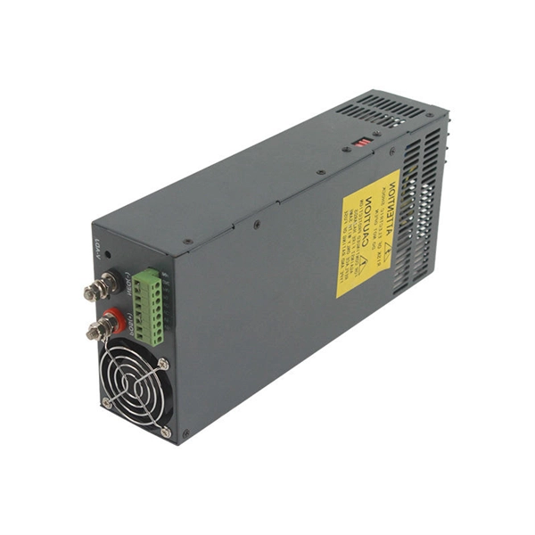
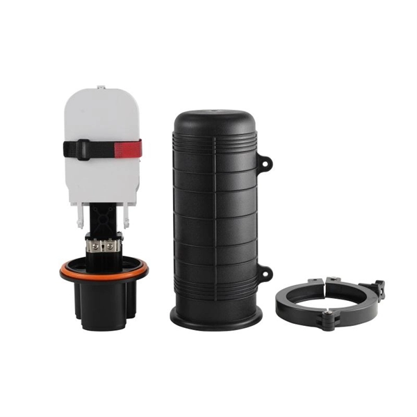
Grounding of the units: Attach a ground wire from one of the threaded studs (A) at the bottom of the housing, to the mounting plate (B). The ground resistance between. This section applies to grounding of transmission and distribution lines and equipment for the purpose of protecting employees. Note to paragraph (a): This section covers. Learn what OSHA requires for electrical grounding in general industry and construction, and what violations can cost you. OSHA's grounding requirements are spelled out primarily in two sets of regulations: 29 CFR 1910 Subpart S for general industry workplaces, and 29 CFR 1926 Subpart K for. Power from factory ground must be installed by a qualified electrician. Each DISTRIBUTION BOX and controller must be grounded. On the US market, a 5. 26 mm 2 (10 AWG) ground wire must be used, and in all other markets a 6 mm 2 must be used. The lockout/tagout procedure must consider several factors, one of which is grounding. Sometimes, installing temporary protective grounding is necessary. Whether you're a seasoned pro or just starting out, this comprehensive guide will give you practical.
[PDF]
On the US market, a 5. 26 mm 2 (10 AWG) ground wire must be used, and in all other markets a 6 mm 2 must be used. Grounding of the units: Attach a ground wire from one of the threaded studs (A) at the bottom of the housing, to the mounting plate (B). Attach a second grounding wire from the mounting. The correct connection method of Distribution box grounding wire mainly includes the following steps: 1. Find the grounding bar or PE bar Open the distribution box and find the position marked with the grounding plate or PE letter. The basic rule achieves this through an equipment grounding jumper; four exceptions. An equipment grounding conductor passing through the box without a splice is not required to be joined inside the box to others that are spliced in the box. 148 addresses the continuity of equipment grounding conductors and their attachment in boxes. Not all boxes are metal or provide. Correct grounding of services depends upon understanding the definition and role of the grounded conductor. The neutral conductor is typically the grounded conductor connected to the system's neutral point, carrying current under normal operation. Whether you're a seasoned pro or just starting out, this comprehensive guide will give you practical.
[PDF]
On the US market, a 5. 26 mm 2 (10 AWG) ground wire must be used, and in all other markets a 6 mm 2 must be used. Grounding of the units: Attach a ground wire from one of the threaded studs (A) at the bottom of the housing, to the mounting plate (B). Power from factory ground must be installed by a qualified electrician. Each DISTRIBUTION BOX and controller must be grounded. In the low-voltage three-phase four-wire neutral point directly grounded line, the construction unit should. Repeated grounding can be grounded directly from the neutral line or from the housing of the zeroing device. It looks like two lines, and in fact they are all together. The main functions of repeated grounding are as follows; (1) Reducing the ground voltage of the leakage device housing. In the. Today, we're diving deep into the world of distribution box grounding, breaking down the standards, and shining a light on those sneaky mistakes that even experienced electricians sometimes make. Good equipment grounding ensures personnel safety. Most North American distribution systems have a neutral that acts as a return conductor and as an equipment. This paper is intended to address how grounding system effectiveness affects each of these goals. Key Words - Grounding, Earthing, Safety, Surge Protec-tion, NESC, Neutral-to-Earth Voltage, Ground Currents, Stray Voltage. This paper is intended to give an overview of the vari-ous relationships.
[PDF]
To help you achieve stable and reliable 800G connections between different brands and models of equipment, we have prepared this concise selection guide. As network speeds escalate to 400G and 800G, proper cabling infrastructure becomes critical for maintaining signal integrity and maximizing performance. Extreme Networks cables provide optimized solutions for high-speed data centers, offering reliable connectivity for next-generation applications. A reliable sourcing strategy must prioritize Multi-Source Agreement (MSA) compliance, rigorous EEPROM compatibility. 800G Ethernet DAC cables, as a direct-connection solution based on high-speed copper cabling, are widely used in short-distance connection scenarios within racks and between adjacent racks. With their simple structure, low power consumption, and convenient deployment, DACs provide a cost-effective. This article provides a comprehensive overview of FS's 800G transceivers and DAC/AOC cables, including product lists, advantages, and application scenarios, offering tailored network solutions for data centers. FS provides a comprehensive portfolio of 800G optical transceivers and DAC/AOC cables. At 400G, interconnect selection was a two-step process: measure the distance, pick copper or fiber. Passive copper comfortably reached 3–5 meters. Multimode fiber handled everything from the rack to the end of the row. 800G changed the underlying physics.
[PDF]
This article deals with a thorough investigation of the energy internet towards future emerging technologies for energy distribution and management to solve existing limitations and enhance the performanc.
[PDF]
This article summarizes the latest fiber optic price data as of March 9, 2026, along with the recent timeline of price changes and the factors behind the surge. Before looking at the price, it is important to explain the source of the price data. What Factors Affect Fiber Optic Cable Pricing? Several factors influence how much you'll pay for fiber optic cables: Fiber Type and Count: Single-mode fiber typically costs $0. 50 per foot for the cable itself, while multimode fiber ranges from $0. Main cost drivers include cable grade (indoor vs outdoor, armoured), distance, and labor for trenching, splicing, and termination. This guide presents ranges in USD and practical price estimates to help. Fiber optic cables are essential components in today's broadband, FTTx, and data center networks. Many global fiber optic giants, such as Corning and. Let's be real: If you are wondering “how much does fiber optic cable cost” for your next project, you've probably seen quotes that make zero sense. One supplier in your inbox promises $0. 05 a foot, while a domestic distributor is asking for ten times that. You search “how much does fiber optic. CRU provides comprehensive, accurate and up-to-date price assessments and research reports for bare optical fibre across various key regional markets, combined with insights into the factors and events affecting markets.
[PDF]
We experimentally demonstrate 100 Gb/s bidirectional transmission over 40 km using a multi-wavelength bidirectional optical sub-assembly (BOSA) based on a single bidirectional multi-wavelength Mux/Demux. The Mux/Demux consists of an optical zig-zag glass block and thin film. A bidirectional SFP (BiDi SFP) provides an efficient solution by enabling data transmission and reception over a single strand of optical fiber. This physical-layer design instantly doubles existing cable plant capacity without requiring expensive new. BiDi optical modules can do this by utilizing full-duplex communication over a single fiber strand via two wavelengths. By reading this blog, you will understand how SFP BiDi technology allows you to save fiber, reduce costs, and simplify installation while enabling your network to increase. In the world of transceivers, BiDi stands for Bi-Directional. In terms of SFPs, BiDi transceivers transmit at one wavelength and receive at another. BiDi SFPs connect to a fiber cable using only one. A 1G BiDi transceiver solves these challenges through single-fiber bidirectional transmission, giving networks a more economical and efficient upgrade path.
[PDF]