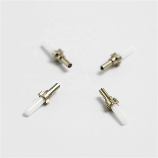
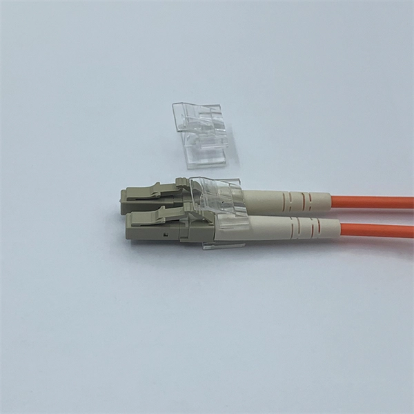
Fiber optic connectors can be categorized according to different standards such as utilization, fiber count, fiber mode, and transmission method. They are also divided into single-mode and multimode types based on their distinct characteristics. The fiber connector types, sometimes referred to as terminations, link fiber optic cables together through terminals, switches, adapters, and patch panels, by bridging the gap between their internal glass fibers that transmit the data down the length of the cable. And based on the connector construction, LC connector also can be divided into LC duplex and simplex connector. a single mode fiber (SMF). And it has a “square shaped” connector body, which is the source of name “square connector”. Due. Fiber optic connectors, according to the different transmission media, can be divided into common silicon-based fiber single-mode and multimode connectors, and other such as plastic as the transmission medium of fiber optic connectors; according to the connector, structure form can be divided into:. A fiber optic connector is a mechanical device used to align and join optical fibers, enabling light to pass through with minimal loss. Simplex vs duplex fiber connectors, single mode vs multimode fiber connectors, what's the difference? This article will explain the above to you.
[PDF]
EIA/TIA 568 B allows any fiber optic connector as long as it has a FOCIS (Fiber Optic Connector Intermateability Standard) document behind it. Fiber optic cold connection, also known as mechanical splicing, is a widely used method of connecting optical fibers in a network. Unlike fusion splicing, which uses heat to join two optical fibers together, cold connection uses mechanical means to create a stable and low-loss connection. Unlike fiber splicing, which is permanent, connectors allow for easy connection and disconnection of cables, making them ideal for maintenance and flexibility in. Fiber optic joints or terminations are made two ways: 1) splices which create a permanent joint between the two fibers or 2) connectors that mate two fibers to create a temporary joint and/or connect the fiber to a piece of network gear. These terminations must be of the right style, installed in a. Fiber termination refers to the process of preparing the end of a fiber optic cable to connect to another fiber, a device, or a network. Proper termination is essential for ensuring optimal performance, reducing signal loss, and maintaining the durability of the connection. Since the introduction of fiber optic technology decades ago, a variety of connector types have been.
[PDF]
Passive media components such as cables, cable splices, and connectors cause attenuation. Although attenuation is significantly lower for optical fiber than for other media, it still occurs in both multimode and single-mode transmissions. Two fundamental mechanisms cause attenuation inside the fiber itself: absorption and scattering. These are intrinsic to the glass, meaning they exist even in a perfectly manufactured, perfectly installed fiber. Scattering is the bigger factor at the wavelengths most networks use. The silica glass. Optical attenuation is the gradual loss of flux (light intensity) as an optical signal travels through a fiber. Measured in decibels (dB), it's the logarithmic ratio of the output power to the input power. Every network has a "loss budget". F iber optic networks rely on the efficient transmission of light signals to deliver high-speed data over long distances. However, various factors can cause signal degradation, leading to performance issues and reduced network reliability. You may see slower speeds and less steady connections when signal loss goes up. Things like impurities in the fiber core and reflections at the core-cladding edge cause this drop. This can be due to a variety of factors: scattering and absorption, intrinsic. Signal attenuation in fiber optics is a key concept in telecommunications. It affects how far a signal can travel without losing.
[PDF]
In this guide, we'll walk you through the entire process of preparing fiber optic cable for splicing and termination to fiber connectors. We'll explore the necessary tools, safety precautions, and step-by-step procedures for cable connectors, mechanical and. This article will guide you through the necessary tools, materials, and methods on how to connect fiber optic cables effectively, ensuring you achieve optimal performance from your fiber optic network. Have a network installation project? Fiber Optic Cables: The primary medium for your connections. There are many types of fiber optic connectors, including SC, LC, FC, ST, D4, MU, MT/MPO, etc. These connectors can be divided into single-mode and multi-mode fiber optic connectors according to their structure and purpose. Fiber optic connectors play an essential role in the realm of optical communication, enabling seamless connections between fiber optic cables. At the heart of any robust fiber optic network lies a crucial process: Preparing a fiber cable for termination of a connector or splice. Whether you're installing a new network, expanding an existing one, or. Fiber optic internet delivers blazing-fast speeds and reliable connectivity, making it a top choice for modern homes and businesses.
[PDF]
The simplest method: connect two cables pre-connectorized via a coupler (also called an adapter). The coupler aligns the two ferrules of the connectors using a zirconia sleeve. Why connect two fibers? Do you need to extend, repair, or connect two fiber optic cables? There are three methods main ones, each with its advantages and limitations. This article explains when. Optical fiber fast connectors, also known as cold connectors, are becoming increasingly popular due to their ease of use and quick installation. Unlike traditional fiber connectors that require epoxy and polishing, fast connectors use a mechanical splice to join the fibers. Another method is using a mechanical splice which involves aligning and securing the fiber ends with a precision. Fiber optic cables can be connected together using a couple of different methods: 1. This creates a permanent and low-loss connection. Connectors play a crucial role in our daily lives, yet there are some connectors that remain less familiar, such as fiber optic fast connectors. The goal is clean.
[PDF]
Positive busbars, which collect all positive connections. Key Steps: When wiring a pair of 12V busbars, connect the positive terminal of each load to a stud on the positive busbar and their negative terminal to a stud on the negative busbar. 5' above batteries on inside of cockpit combing below decks. Install one new positive bus bar beside the negative one separated by about two inches 3. Positive and negative busbars are physically identical apart from the red/black colours used by some manufacturers to visually differentiate between. A Complete Guide to Battery Terminal Connector Types The store will not work correctly in the case when cookies are disabled. JavaScript seems to be disabled in your browser. For the best experience on our site, be sure to turn on Javascript in your browser. Skip to Content Blog Sign In Create an. This image illustrates a standard car battery with top post terminals and labeled connectors for the positive (+) and negative (–) ends, emphasizing safe and correct installation. A battery terminal connector is a fitting or clamp that attaches to a battery's terminal to connect a cable. In other. Both positive and negative terminals are the soul of the electrical system of the car, allowing the engine to start while keeping other components running. The catch? Mix-up or loose connection can cause electrical failure, drained batteries, and damage to wiring. This blog guides you how the two.
[PDF]