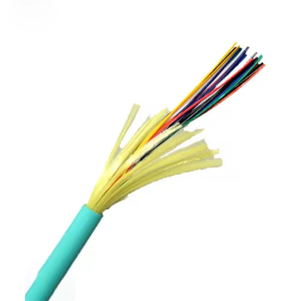
For singlemode fiber, the loss is about 0. 5 dB per km for 1310 nm sources, 0. 5 dB/km at either wavelength for outside plant max per EIA/TIA 568)This roughly translates into a loss of 0. 1 dB per. ity check. The fiber optic link attenuation is tested using an optical loss test set (OLTS) or a light source and power meter (LSPM) Figure 1). This type of testing is the most accurate testing available and is the most accurate characterization of the fiber optic system's apability. The estimate, called a "loss budget" is calculated using typical component losses for. Many solutions for 100 Gbit/s Ethernet have proposed to use CWDM to carry the multiple lanes over separate wavelengths on a single fibre. The presentation from Monterey anslow_01_0107. wavelength to justify the choice of CWDM channels to be analysed. It was. This document outlines the specifications for a single-mode optical fiber and cable designed for use around the 1310 nm zero-dispersion wavelength, suitable for both the 1310 nm and 1550 nm regions, and compatible with analogue and digital transmission. The acceptable dB loss for single mode fiber can vary depending on several factors. Measured in decibels (dB), insertion loss is the reduction in signal power that happens along any length of cable for any type of transmission. The longer the cable, the more a signal is reduced (or attenuated) by the time it reaches the far end. In addition to length, events that cause reflections.
[PDF]
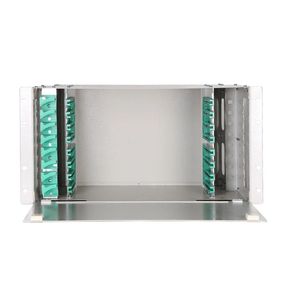
The devices has a wide pass band, low insertion loss, high channel isolation and excellent environmental stability. Channel numbers can be as high as 40 (16) for 100 (200)GHZ systems in C band or in L band. They can be used in DWDM systems to perform a multiplexing or. Fiberdyne Labs offers Dense Wavelength Division Multiplexer (DWDM) Modules in a wide variety of formats. While Fiberdyne offers some models as "standard," we will also produce customized DWDM modules. Customization can include the number and selection of DWDM channels. Channel. AFL's DWDM LGX modules provide scalable wavelength management for new deployments and network upgrades, providing increased bandwidth over a single common fiber. Based on thin film filter technology, the device is less than one-third the size of traditional cascaded DWDMs of similar channel count. Modules can be installed in standard LGX chassis and are available with LC bulkheads in select. All parameters are for device without connectors 2. Special specifications can be customized according to customer requirements DWDM mux demux and optical modules for high-capacity fiber networks. 40/80-channel options, rack mount or LGX type, low insertion loss, high stability. Ideal for telecom.
[PDF]
This document describes how to use and program the Photonic Application Suite, Insertion Loss Engine. Insertion loss is measured by comparing signal power (or sound level) before and after it passes through a component or system, then expressing the difference in decibels (dB). The core process is the same across fiber optics, RF electronics, and acoustics: establish a baseline reference without. This tutorial aims to help RF engineers understand how to test and measure various RF specifications of RF power amplifiers, RF LNAs (Low-Noise Amplifiers), and RF transceivers using RF test and measurement equipment like spectrum analyzers, signal generators, and sweep oscillators. Gain is the. Coaxial cables are essential components in transmitting radio frequency (RF) signals, but they inherently attenuate these signals, a phenomenon known as cable loss or insertion loss. Yes, I would like to receive educational or promotional emails from Keysight. By clicking the button, you. Insertion loss is a critical parameter in RF engineering that refers to the loss of signal power that occurs when a component or device is inserted into a transmission line or circuit. The insertion loss measurement quantifies the effect of the resistance the cabling link offers to the transmission of the electrical signals. Insertion loss characteristics of a.
[PDF]
ITU & IEC allow 0. 75 dB loss per mated pair. Splitter loss values are "Typical" and include a connector in and out. These values are approximate and should not be exceeded by more than 1-1. 5 dB, which could indicate dirty connectors, bad splices . ITU & IEC allow 0. Passive split links usually lose the most dB at the splitter, so we keep the optical budget and the installed route separate. Measured in feet for imperial mode. Drop length Adds. Calculate split loss, excess loss, and terminations for any ratio quickly today. See power budget impact instantly, then download a CSV or PDF summary. Use 2×N when two inputs feed the same distribution stage. Common values: 2, 4, 8, 16, 32, 64. Abridged Optics — Beam Splitter Calculatorv1. 0Fresnel calculations assume a single uncoated interface. Real beam splitters use multi-layer coatings that modify R/T beyond Fresnel predictions. Understanding the types of splitters, their impact on network performance, and how to measure their losses ensures high-quality network operation and facilitates optimal splitter selection based on. This value should be determined by the system designer. 3 recommends a maximum value of 0. Total Splice Loss (The maximum splice loss permitted for installation. Components, such as fiber cables, splitters, and switches, introduce attenuation.
[PDF]
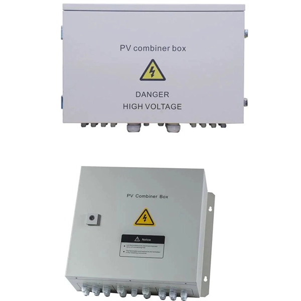
Key cost drivers include panel amperage, indoor vs outdoor location, wiring length, and whether a full panel upgrade or rerouting is needed. The article outlines cost ranges, per-unit pricing, and practical budgeting notes for U. Buyers typically pay for a full panel replacement, including labor, materials, and permits. Whether you are a seasoned procurement officer or a first-time project manager, understanding the distribution box market is about more. Buyers typically pay a broad range for replacing a distribution box, driven by box size, amperage, wiring runs, and local labor rates. The cost includes materials, labor, and possible inspections or upgrades to meet code requirements. This article breaks down the price so buyers can estimate a realistic. Distribution box cost encompasses various factors that influence the overall investment in electrical distribution systems. A distribution box serves as a crucial component in electrical installations, housing circuit breakers, fuses, and other protective devices that ensure safe power distribution. It typically costs about $1,000 to replace one, though the cost can range from $500 to $1,500. In this cost guide, we outline what you'll need to budget for your septic distribution box replacement costs.
[PDF]
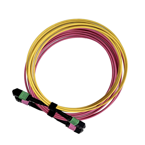
This article provides an in-depth exploration of OSFP copper cable technologies, including DAC, ACC, and AEC, with a focus on 400GB NDR splitter cable applications. Whether the signal is propagated by copper wire, optical fiber, Wi-Fi, or just yelling at the kids down the street, the signal is never as strong at the destination as it is at the source. In the case of physical voice communication, the kids will understand you if they are close-by. If they are. Insertion loss and attenuation are similar concepts, but one is assigned to a single component (insertion loss) whereas the other is assigned to generalized performance (attenuation). Both terms refer to a measurement comparing the signal strength received against a transmitted signal. Standard. Channel Master TV splitters are designed to equally divide the signals on the input port of the splitter to each of the output ports of the splitter. This. Insertion loss is the amount of energy that a signal loses as it travels along a cable link. It is a natural phenomenon that occurs for any type of transmission—whether it's electricity or data. This reduction of signal, also called attenuation, is directly related to the length of a cable—the. In fiber-optic networks like FTTx and PON, PLC splitters are key components for distributing optical signals to multiple users. However, each splitter has complex parameters, including insertion loss, return loss, polarization-dependent loss, and uniformity.
[PDF]
With vast rural areas lacking grid access, battery energy storage systems (BESS) provide reliable electricity for communities and industries. Imagine a solar farm in the Andes storing excess dayt Bolivia's growing energy demands and remote terrain make the BESS outdoor power . As Bolivia's fastest-growing urban center, Santa Cruz faces unique energy demands that require robust outdoor power solutions. Whether you're a homeowner seeking backup options or a business owner. Imagine a solar farm in the Andes storing excess dayt. The world"s largest PV-diesel hybrid power plant system with battery storage was commissioned in December 2014, in the Bolivian province of Pando. SMA is not only supplying photovoltaic inverters Bolivia"s growing industrial and commercial sectors demand stable power solutions. Whether you're a homeowner seeking backup options or a business owner. Aug 13, 2025 · How We Selected and Tested To pick the best solar generators, we tested some of these power stations for charging capacity, Aug 29, 2025 · Bolivia"s solar development has reached a new height of a 3MW ground solar project, the largest solar plant in the private sector within the. If you are looking for Electrical Panel, we have LT Distribution Panel, Load Management Panel, Outdoor Power Panel, Marshalling Panel, and Power Control Panel In Bolivia. So get in touch with us for your Panel need. An electrical cable is a current-carrying assembly of wires that runs side by side.
[PDF]
This application note explains how Site Master is used to measure cable insertion loss with different test methods and how to predict the maximum allowable cable insertion loss through manual calculations. Desktop Insertion Return Loss Tester with color screen has stable and reliable performance, which integrates stable light source, high-precision power meter, insertion loss meter and return loss meter into one multifunction instrument. Based on domestic customers'. Modern handheld analyzers, like the Keysight FieldFox Analysers, are designed specifically for cable and antenna testing (CAT), offering fast and accurate insertion loss testing across a wide frequency range. These tools are invaluable for both installation and maintenance, enabling field. Insertion loss is expressed in decibels or dB. The decibel is a logarithmic expression of the ratio of output voltage (voltage of the signal received at the end of the link) divided by input voltage (the voltage launched into the cable by the transmitter). 0 PCB transmission line losses in a PCB production environment. In wireless communication systems, the transmit and receive antennas are connected to the.
[PDF]
The optical budget refers to the maximum allowable signal loss between the transmitter and receiver in a fiber-optic link. It ensures that the received signal is strong enough for the equipment to process data without errors. Calculated in decibels (dB), it is the difference between the. After measuring the loss of a fiber link, you now have to determine if that fiber link loss is acceptable or not. You can either compare this loss value to the application requirement or calculate the expected loss based on how many connectors and splices are in the link along with the length of. Optical module channel loss resistance refers to the maximum optical path attenuation that an optical transceiver module can tolerate while still maintaining compliant signal integrity, error performance, and link stability. There are many reasons for optical fiber loss, such as optical fiber material's absorption/scattering of light energy, bending.
[PDF]
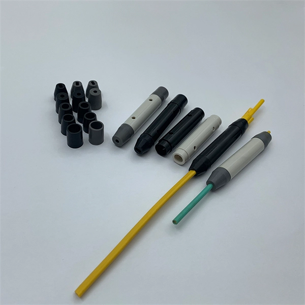
Engineered with tight mechanical tolerances and high reproducibility, the F‑SMA ensures consistent insertion loss (~0. 8 dB) and return loss (~12 dB), suitable for both standard and power-intensive applications. The SMA-905 Connector, also know as FSMA Connector, was one of the first fiber optic interconnect system that gained industry wide acceptance. Today the connector is still widely used for military, industrial, and medical applications. Our SMA-905 Connectors have a threaded coupling nut and feature. The SMA connector family utilizes a threaded coupling nut system for mating and de-mating. Available with zirconia or stainless steel ferrules with custom hole sizes, the SMA is an excellent choice for a robust, low-cost and reliable system. Features: Reliable, robust and time-tested as one of the. Note: In fiber optics, a single connector has no loss. The "loss of a connector" is defined as a "connection loss" caused by a mated pair of connectors. The lab method used to establish the average loss value of a connector design is shown below. For free-space optics, the F‑SMA Interface Module (IMOD) adapter provides precise. Return loss and VSWR (Voltage Standing Wave Ratio) are measurements for the same parameters; they have a logarithmic transition; see this link for a comparison table of return loss and VSWR. Its high-precision, ceramic ferrule allows its use with both multimode and single-mode fibers. The bayonet style, keyed.
[PDF]
Buyers typically pay a broad range for replacing a distribution box, driven by box size, amperage, wiring runs, and local labor rates. This article outlines the cost factors, price ranges, and practical budgeting advice for a U. In the world of electrical contracting, you have to estimate and submit bids in order to win projects and stay in business. This means bidding low enough to win against many competing electrical contractors, while high enough to cover all the project costs like labor, material, equipment. As an electrical contractor, you must account for materials, labor, subcontractors, and equipment while ensuring costs stay within budget and deadlines are met. Electrical estimating involves reviewing project specifications, calculating material quantities, considering overhead, turnkey estimates. Estimating electrical work — particularly in the context of new construction projects or extensive commercial service jobs — involves many steps and moving pieces. Whether you're quoting a panel upgrade or a full-scale buildout, every detail in your estimate shapes the bottom line. Create professional electrical project estimates with localized material pricing, labor rates, and tax calculations. Supports US (USD), Canada (CAD), and UK (GBP) markets with region-specific electrical components and standards. Accurate cost estimating is essential for profitable electrical work. Understanding cost components helps avoid surprises in.
[PDF]