Mechanical splicing is a method of connecting two optical fibers without using heat or a fusion machine. Instead, it uses a small plastic or metal device to hold the fiber ends tightly together. A special index-matching gel is often used inside the splice to help light pass through the connection. You can manually splice the fiber patch cord with the help of the Procedure shown in the video. Now you can splice your patch cord. For network managers and technicians, a poor splice can lead to significant signal degradation, network downtime, and costly troubleshooting. At Turn-Key. This wikiHow article teaches the process of manually splicing patch cords and fusion splicing two fiber optic strands together in an 11-step process. The video also demonstrates how to fix a cut or. Fiber cable splicing is a critical step in building reliable fiber optic networks. Whether in data centers, telecom rooms, or outdoor FTTx deployments, proper splicing inside a fiber enclosure ensures low signal loss, long-term stability, and easy maintenance. This guide explains what fiber cable. In this guide, we cover the basics of fiber optic splicing, how to perform splicing using two different methods, and finally some best practices to perform good fiber splicing. What is Fiber Optic Splicing and Why is it Needed? – #1. Use and Maintain Your.
[PDF]

On average, a single fusion splice can take anywhere from 10 to 30 minutes, including preparation and testing. The answer isn't always straightforward, as it depends on various factors, including the type of fiber, the splicing method, and the level of expertise of the technician. Before we dive into the timeline, it's essential to understand the splicing process itself. Fiber splicing involves several. Fusion splicing refers to a method of joining two optic fibers together by means of heat, often an electric arc, which fuses the glass ends. It is the technique that has the least insertion loss and almost no back reflection, hence ensuring strong connections over a long period. A welding machine. This is typically done when the cable length is insufficient or when the fiber network is damaged and needs restoration. Unlike connectors, which are used for temporary joints, splicing creates a permanent, low-loss connection. This process is essential in telecommunications for extending network reach or repairing damaged sections without replacing entire cables. Splicing preserves the integrity and efficiency of the fiber optic network, offering a cost-effective solution for. A chart developed by Fiber Optic Association master instructor Joe Botha helps technicians calculate the amount of time it will take to conduct a fusion-splcing project. The FOA mentioned the chart in its November 2011 newsletter, stating, "We've been asked many times, 'How long does it take to.
[PDF]
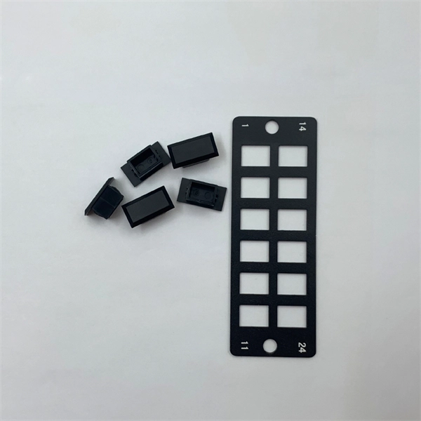
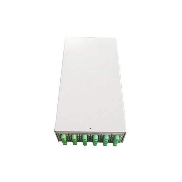
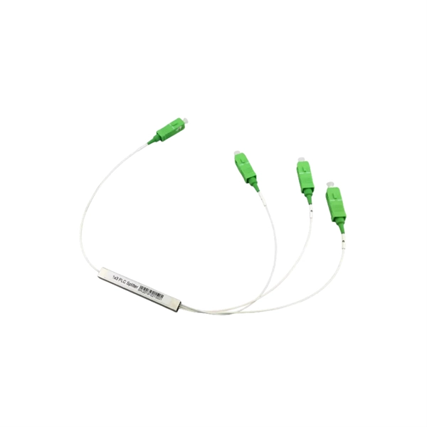
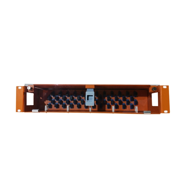
A splice box (also known as splice distributor) is a housing in which fiber optic cables begin or end. Fiber optics are fanned out in splice boxes that are situated at the end of fiber optic transmission paths. It typically consists of two parts: an outer housing and an internal structure. The main components of a splice box are the splice cassette that picks up the fibers and. The fiber optic dome splice closure is well-suited for splicing, distributing variable optical cables, and splitting. The solid box shell and the main structure are built to withstand harsh environments. The dome closure also protects fiber optic cables from vibration, impact, stretching, twisting. Home » Professional Insights » Fiber Optic Splice Closure: A Complete Guide to Types, Structure, Applications, and Selection In real fiber optic networks, cables are rarely installed as one continuous, uninterrupted length. Along transmission routes—whether in access networks, metro networks, or. Big space for managing pigtails or splitters. The 12 Port Fiber Distribution Box can connect up to 2 optical cables, providing space for distributors and 12 fuses. It is equipped with 12 SC adapters and can work in outdoor environments. Data communication networks. Horizontal fiber optic splice closures, also known as optical cable splice boxes, play an important role in the communications industry. It is a must-have device in the construction of optical cable line projects.
[PDF]
Fiber splice closures are not used occasionally — they are deployed extensively across every fiber network. The exact quantity depends on population density, network topology, and regional infrastructure planning. There are hundreds of different designs and options on splice closures. Some are designed for concatenation of long distance cables where two identical cables are spliced together. Its role is not only to enclose the splice, but to ensure that optical performance remains stable throughout years of operation. In FTTX and outdoor access networks especially, the reliability of. There are several types of fiber optic splice closures available in the market, each designed for specific applications and environments. There are many possible ways to put two or more cables together or drop a single fiber at a location. It creates an air-tight environment that safeguards these splices from environmental considerations, including wetness, dust, and temperature changes; hence, the. CommScope addresses these challenges with a comprehensive family of fiber splice closures that prioritize essential criteria: reliability, installability, flexibility, and speed of deployment. Trunk and Feeder Network Solutions: These closures are designed for robust performance in the backbone of.
[PDF]

In this guide, we'll walk you through the entire process of preparing fiber optic cable for splicing and termination to fiber connectors. We'll explore the necessary tools, safety precautions, and step-by-step procedures for cable connectors, mechanical and fusion. Think of a fiber optic cable splice as the seamless stitching that keeps data flowing through the delicate threads of a network—like a master tailor joining fabric with precision. Whether repairing a broken cable or extending a fiber run, fiber optic splicing ensures light signals travel. Splicing fiber optic cable is an extremely important phase for making dependable, high-speed communication infrastructures. Regardless of the type of fiber network you're deploying, be it for telecom, enterprise data centers, or smart city infrastructure, fusion splicing provides the benefits of. This guide reveals the secrets to fusion splicing with little fluff—just proven, straightforward techniques refined from years of work in the field. The guide provides the complete workflow, covering safety precautions, tool selection, fiber preparation, fusion operation, quality control, and. Executive Summary: A fiber optic pigtail is one of the most commonly specified yet least understood components in structured cabling. What is Fiber Optic Splicing and Why is it Needed? – #1.
[PDF]
The core principle of fiber optic splicing is to achieve low-loss, high-strength junctions between fiber ends. This involves three key steps: preparation, alignment, and bonding. Let's break it down technically:. At the core of this system's precision and reliability are Fiber Optic Splice Boxes—the unsung heroes that house and protect the delicate junctions where fiber cables are joined. The integrity of these enclosures is paramount to network performance. This guide optimizes the original text by delving. A splice box (also known as splice distributor) is a housing in which fiber optic cables begin or end. Key Functions Typical Applications ZION FTB Highlights In essence: The Fiber Terminal Box is an end-user termination device for small-scale distribution. ■ What Is a Fiber. Fiber optic cables are the lifeline of modern telecommunications, delivering high-speed data with minimal loss. However, installing and maintaining these networks requires seamless connections between fiber segments—a process known as fiber optic splicing. Understanding how it works is essential for anyone interested in telecommunications or network infrastructure. Essential for mending faults or scaling networks, splicing underpins the backbone of contemporary communications. In this comprehensive guide.
[PDF]
Distance relays, also known as impedance relay, differ in principle from other forms of protection in that their performance is not governed by the magnitude of the current or voltage in the protected circuit but rather on the ratio of these two quantities.OverviewIn, a protective relay is a device designed to trip a when a is detected. The first protective relays were electromagnetic devices, relying on coils operating on moving par. Electromechanical protective relays operate by either, or. Unlike switching type electromechanical with fixed and usually ill-defined operating voltage thresholds. Electromechanical relays can be classified into several different types as follows: "Armature"-type relays have a pivoted lever supported on a hinge or knife-edge pivot, which carries a moving contact. These relays may.
[PDF]
Find Brazilian high low voltage electrical apparatus importers on ExportHub. How does 6Wresearch market report help businesses in making strategic decisions? 6Wresearch actively monitors the Brazil Electric Power Transmission & Distribution Equipment Market and publishes its comprehensive annual report, highlighting emerging trends, growth drivers, revenue analysis, and. The Impact of COVID-19 is included in the Electric Transmission and Distribution Equipment Market in Brazil. Buy it today to get an advantage. The future of the electric transmission and distribution equipment market in Brazil looks promising with opportunities in the power utilities, residential. Are you a seller? Add your own products to Allbiz as well!. Find Brazilian high low voltage electrical apparatus importers on ExportHub. Global Brazil High and Low Voltage Cabinet Market Size, Strategic Opportunities & Forecast (2026-2033) Market size (2024): USD 7. 5 billion · Forecast (2033): USD 10. 2% Brazil High and Low Voltage Cabinet Market Growth Matrix: Drivers, Limitations & Opportunity Landscape Major. 44 comprehensive market analysis studies and research reports on the Brazil Power Transmission and Distribution sector, offering an overview with historical data since 2019 and forecasts up to 2030. This includes a detailed market research of 770 companies, enriched with industry statistics.
[PDF]
This video shows real on-site footage of electrical installation, demonstrating safe and standardized wiring methods used by professionals. more Learn how to wire a distribution box step by step!. A distribution box, also known as a distribution board, electrical panel, or breaker box, is an enclosure that houses electrical components responsible for distributing electricity throughout a building. more Learn how to wire a distribution box step by step! This video shows real on-site footage of. In this video, we'll walk you through the process of wiring a home distribution box with a detailed connection diagram. Whether you're an electrician or a DIY enthusiast, this guide will help you understand the basics of home electrical distribution. What is Distribution Board? Distribution board. Connection method: Each switch takes a wire from the incoming point and connects it to the incoming end of the switch, or uses parallel connection to reduce the difficulty of wiring. Wiring Direction: Wiring between the main circuit breaker and each branch circuit breaker in the box generally. Understanding the wiring diagram of an electrical panel box is essential for electricians and homeowners alike, as it allows them to troubleshoot any electrical issues, carry out repairs, or make additions to the system. It takes the incoming power and safely distributes it to different circuits throughout your building. However, the key to.
[PDF]
The article provides an overview of protective relaying principles and their applications for high-voltage power system components. It covers the protection methods for generators, transformers, buses, and transmission lines using various relay types to detect and. Protective relaying is the backbone of fault detection and system isolation in As transmission systems grow increasingly complex with integration of renewables and smart technologies, the design, configuration, and application of protective relays have become more critical than ever. This article. tensify their search for reductions in capital investment and operating expenses. Faced with the continuing demand for more and more power in an environmentalist era, many operating companies are seeking, among other things, a means for supplying eliable power with fewer transmission lines and. SIPROTEC 7SD82 provides compact, cost-optimized line differential protection for medium- and high-voltage systems. It ensures safety with 3-pole tripping in 19 ms and high availability via conformal coating. The modular SIPROTEC 7SD86 is specifically designed for line differential protection of. Still deciding? Get samples first! Order sample Still deciding? Get samples first! Order sample. In HV (High Voltage) and MV (Medium Voltage) substations, relay protection safeguards critical assets such as transformers, circuit breakers, and lines. Effective relay protection depends on.
[PDF]
This report offers comprehensive insights, helping businesses understand market dynamics and make informed decisions. Do you also provide customisation in the market study? Yes, we provide customisation as per your requirements. To learn more, feel free to contact us on. How does 6W market outlook report help businesses in making decisions? 6W monitors the market across 60+ countries Globally, publishing an annual market outlook report that analyses trends, key drivers, Size, Volume, Revenue, opportunities, and market segments. This report offers comprehensive. Exports In 2022, Sierra Leone exported $20. 1k in High-voltage Protection Equipment, making it the 126th largest exporter of High-voltage Protection Equipment in the world.
[PDF]
The West African Power Pool (WAPP) aims to provide access to affordable electricity to all countries in the region by installing electricity interconnections between countries and creating an integrated ele.
[PDF]
Voltage/BIL: 35 kV class, typical BIL 170 kV. Short-circuit: 25–40 kA short-time withstand common; confirm with system fault study. Continuous current: 1250–3150+ A bus and feeder options. Standards: IEC 62271-200; internal arc testing per IEC/TR 61641 if specified. The Insulation levels for Distribution, Class 1 and Class 2 transformers shall be selected from this table for both the high-voltage and low-voltage windings. All test levels are line to ground. The applied test levels are not applicable to wye-connected windings unless they have been specified to. PURPOSE: To provide general construction requirements for representative wood pole structures and assemblies for 34. 5 through 69 kV transmission lines. 2-1. Most distribution voltages are between 4 and 35 kV. In this article, unless otherwise specified, voltages are given as line-to-line voltages; this follows normal industry practice, but it is sometimes a source of confusion. A voltage class is. This article is for manufacturing, testing of non-segregated Bus Bars and Bus Ducts rated 600 V to 35 kV as per international standard ANSI C37. Air insulation with generous. Rated maximum voltage, kV BIL, kV Manufacturing Date: MM/YYYY Rated continuous current, A Rated load interrupting rating, A Momentary current rating, kA asym. Close & latch rating, kA asym. Liquid dielectric volume (gallons) – Liquid-Filled Units Only SF6 Weight, Pressure – SF6.
[PDF]
There are more than ten proprietary implementations. The more common ones are discussed below. Some Cisco WLAN access points and supported a proprietary form of PoE many years before there was an IEEE standard for delivering PoE. Cisco's original PoE implementation is not software upgradeable to the IEEE 802.3af standard. Cisco's original PoE equipment is capable of delivering up to 10 W per port. The amount of power to be delivered is negotiated between the endpoi.
[PDF]
Protection: CVTs supply voltage signals to protective relays, enabling them to detect faults and initiate appropriate actions, such as circuit breaker tripping. Control: CVTs can also be used in control systems to monitor voltage levels and provide feedback for voltage regulation. Capacitive Voltage Transformers (CVTs) are common in high-vo tage transmission line applications. These same applications require fast, yet secure protection. However, as the requirement for faster protective relays grows T models whose purpose is to identify which major CVT components contribute. ve Voltage (CVT) and Capacitance Coupled Voltage Transformers (CCVT). With this comprehensive range of accurate power sensing devices coupled with GE's vertical integration approach and skilled design engineering staf, we work closely with our globa ems for applications ranging from high-voltage to. Capacitive Voltage Transformers (CVTs), also known as capacitor voltage transformers, are essential components in high-voltage power systems. They provide a cost-effective and reliable means of measuring voltage and supplying power to protective relays and metering equipment. This essay will delve. Potential transformers and coupling capacitor voltage transformers (CCVT's) have been used successfully for providing voltage to the inputs of meters and relays since the 1960's. It utilizes a capacitive voltage divider in conjunction with an electromagnetic voltage converter to provide a.
[PDF]