o In optical modules, "core" refers to the light-transmitting channel in the fiber. A 1-core module uses a single fiber core for data transmission, while a 2-core module uses two cores. o Think of a highway. A 1-core fiber is like a single-lane road—only one car (or. The secret lies in fiber optic technology, and understanding the basics—1-core, 2-core, Single Mode (SM), and Multi-mode (MM)—is key to mastering this field. Let's break down these terms in simple, clear language with practical examples. Definitions · 1-core vs. A. SFP (Small Form-factor Pluggable) is a compact, hot-pluggable network interface module used to connect network devices (switches, routers, firewalls) to fiber optic or copper cables. Think of it as the “translator” for your network equipment, converting electrical signals into optical signals. An optical transceiver is a modular device that serves as both a transmitter and a receiver (hence the name). In fiber optics, the data is sent in the form of light pulses or signals at high speeds and over long distances. The fiber optic transceivers convert the electrical input received from.
[PDF]
Fiber optic switches utilize specialized ports such as XFP, SFP, CFP, SFP+, or QSFP+ to connect to fiber optic cables. These ports aren't directly compatible with the cables themselves; they require transceiver modules. SFP/SFP+ Modules: Small Form-factor Pluggable (SFP) modules are transceivers that connect the switch to the fiber optic cables. The choice between SFP and SFP+ depends on the network speed requirements, with SFP+ supporting higher speeds (up to 10 Gbps). Fiber Optic Patch Panels: These are used to. Choose an SFP module based on the fiber optic cabling that will be connected to the network switches. Always integrate duplex (two strand) fiber optic cabling or higher strand counts. The process requires understanding the type of fiber optic port on your switch and selecting the appropriate transceiver module. Always. I wish to connect (single mode) fibre optic cable to Fibre optic switch ( DIN-rail mounted) directly without using patchl panel or patch cords. I would also like to know what precautions should be taken during cable terminations. This is due to no or less space available for patch panels in my. The process of connecting fiber optic cables to network switches involves meticulous attention to detail and adherence to industry best practices to ensure reliable data transmission and seamless network connectivity. Before commencing the connection process, it is essential to ascertain the.
[PDF]
The mlxlink tool is used to check and debug link status and issues related to them. In order for mlxlink to function properly, make sure to update the firmware version to the latest. In this context, PHY can be understood as an optical module. When testing PRBS, there are 3 test nodes: MAC ----> PHY, PHY -----> MAC, and PHY ----- PHY. Signal testing can be performed through these 3 different nodes. and detection in MAC testing. Example: For device N9200-64DC, test ports. Qualcomm chips are now the core of high-speed optical modules for 5G networks, data centers, and enterprise interconnects. These modules leverage advanced signal processing, modulation, and high-speed interfaces to provide high bandwidth, low latency, and reliable performance. During use, reading optical module information helps understand its real-time operating status, enabling faster troubleshooting of link abnormalities. The following uses the. This article provides instructions on how to view the Optical Module Status on your switch through the Command Line Interface (CLI). The Cisco Small Business Series Switches allow you to plug in a Small Form-factor Pluggable (SFP) transceiver in their optical modules to connect fiber optic cables. mlxlink is. Could you please provide me some steps on how to enable ICMP debug on the 3850 to find the root cause of the problem? Thanks! Hello Eyad There are a couple of things that come to mind that may help you in your troubleshooting.
[PDF]
The SFP optical module is a standardized, modular assembly designed to be quickly installed or removed from a device's port without requiring the device to be powered down. This key feature—being hot-pluggable —is essential for simplifying network maintenance and minimizing downtime. SFP (Small Form-factor Pluggable) is a compact, hot-pluggable network interface module used to connect network devices (switches, routers, firewalls) to fiber optic or copper cables. It converts electrical signals into optical (or copper) signals and vice versa. An SFP transceiver acts as a compact, hot-swappable optical transceiver that. An SFP switch uses Small Form-Factor Pluggable (SFP) modules to form a network switch for high-speed connectivity between devices. These interchangeable modules support various media types, including copper or fiber-optic cables, providing flexible networking options based on specific requirements.
[PDF]
Run the display transceiver [interface interface-type interface-number | slot slot-id] , to view the information on the optical module interface. During use, reading optical module information helps understand its real-time operating status, enabling faster troubleshooting of link abnormalities. The following uses the. Taking the Huawei 5700 series switches as an example, the commands to view optical module information are as follows: Transceiver Type :1000_BASE_SX_SFP Connector Type :LC Wavelength(nm) :850 Transfer Distance(m) :300(50um),150(62. 5um) Digital Diagnostic Monitoring :YES Vendor Name. See the interface module via the optical display command information, including general information of the optical module, manufacturing information, and alarm information. This is tested using NetEngine40E Universal Service Router or NE40E running version 8. Sample Output: (Can see link down and not receiving any power from the neighboring device) Or can do filtering:. Today, ETU-LINK will introduce how to query the information of optical module on Huawei switch. Next, we will introduce the query instructions of relevant parameters of optical module, and view the DDM information of interface optical modules through display command. Execute the command, display.
[PDF]
Frequent status changes from up to down or vice versa in the ports logged by the switch port syslog indicates a port flap. On a big industrial plant we've replaced an old HP switch with a brand new couple of C2960x switches in stack configuration and ever since then, every 6/8 hours or so, the two fiber optics links of switch #2 go down at once. These are connected to a ring of 3 similar other access switches, that. EX4650 2-switch virtual chassis, running version 19. 2, optic p/n 740-031981 (SFP+-10G-LR) is plugged into port xe-0/0/10 and connected to an ISP via single mode fiber. Nothing special is configured on the port, it is running at 10G speed, show interfaces diagnostics optics shows that it's. This article describes steps to diagnose the Continuous port flapping on a FortiSwitch. Verify Cable Connection: Ensure the cable is properly connected between the switch port and the end device. Run the command below on FortiSwitch multiple times and check the. Real head scratcher this morning that I'm hoping someone can help me with! The port on our core switch (HP A5500) that our Smoothwall box is connected to keeps going up and down. Port flapping, also known as link flapping, causes a switch port's state to fluctuate between up and down within concise periods of time. This instability caused by flapping ports affects network connectivity. Port flapping is a common network issue that can disrupt communication between devices and degrade overall network performance.
[PDF]

The short answer is no - RJ45 connectors are designed for electrical Ethernet signals, while fiber optics transmit light pulses through glass or plastic. However, modern networks often combine both technologies. A combo port, also known as an optoelectronic multiplexing interface, is a photoelectric composite port with two kinds of Ethernet interfaces (RJ45 port and SFP port) on an Ethernet switch. In other words, it is a compound port that can support two different physical layers and share the same. Optical ports on switches typically require the insertion of optical modules for data transmission over fiber optics. However, these two different physical ports can not be used at the same time. If you wake up the RJ45 port, the corresponding SFP port will. Ensuring seamless interoperability and compatibility between optical transceiver modules and network devices is crucial for maximizing network performance, reducing downtime, and controlling operational costs. This guide dives deep into the core aspects of optical transceiver compatibility, common. SFP (Small Form-factor Pluggable) is a compact, hot-pluggable network interface module used to connect network devices (switches, routers, firewalls) to fiber optic or copper cables. Think of it as the “translator” for your network equipment, converting electrical signals into optical signals.
[PDF]
The operating principle of an OCS is similar to telephone circuit switching. When two ports need to communicate, the controller configures a path in the optical switch matrix, using optical components to route the optical signal from one fiber to another, forming an independent. Optical switching represents a fundamental technological evolution, shifting data routing from the domain of electrons to the realm of photons, or light. This transition allows data to remain in its native optical form as it travels through fiber optic networks, eliminating the need for. Optical switches are devices that route light signals from one path to another without converting them into electrical signals first. They're a core component in fiber-optic networks, where data travels as pulses of light through glass fibers. Every time that light needs to change direction or jump. Optical switches, a key component in modern network infrastructure, are devices used in optical fiber networks for signal management. Unlike traditional electrical switches, which transmit data as electrical signals, optical switches handle data transmission in the form of light. These devices play a critical role in modern optical networks by enabling dynamic reconfiguration, wavelength routing, and protection switching. In this article, we will explore the fundamentals of optical switches, their types, and their applications in various fields. An optical switch is a.
[PDF]
A PLC splitter is a passive optical device that divides one incoming optical signal from an input fiber into multiple output signals across several output fibers. PLC splitters utilize a planar lightwave circuit chip made of silica glass waveguides to distribute the optical power. PLC optical splitters (planar waveguide optical splitter) is a key component in optical fiber communication networks and is widely used in optical fiber distribution systems such as FTTH (fiber to the home) and PON (passive optical network). This passive yet sophisticated device utilizes integrated optics technology to split a single input signal into multiple. PLC splitter, also called Planar Waveguide Circuit splitter, is a device used to divide one or two light beams into multiple light beams uniformly or combine multiple light beams to one or two light beams. This helps share signals in fiber optic networks. Pick the split ratio that matches what you need. Lower ratios work for fewer users. Choose the connector type like SC, LC, or FC.
[PDF]
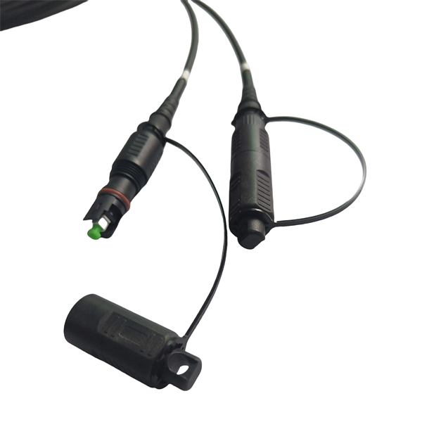
Yes, fiber cables can be bent during installation, which proves particularly useful when you pull cables into position rather than using blown installation methods. Blown fiber installation uses air pressure to propel cables through conduits, minimizing bending stresses. Fiber optic cables are designed to withstand some bending, but excessive bends can physically damage the glass fiber or cause significant signal loss. That's why every fiber cable has a minimum bend radius specification provided by the manufacturer. The minimum bend radius defines the smallest. All fiber optic cables have specifications that must not be exceeded during installation to prevent irreparable damage to the cable. Installers must understand these specifications and know how to install cables without. The bend radius of fiber cables is critical for maintaining high performance and longevity. A practical single-mode fiber option for compact routing, dense fiber management, FTTH access, and reel-based systems such as drone fiber and FPV fiber tether where bend-loss control matters in real installation and maintenance conditions. The tighter the bend, the smaller the radius. The minimum bend. Astel 4 Core Siamese model has 2 x 2 Fiber cables joined in the center by steel messenger. Its main advanctage is that a single cable can be used for 2 independent telecom operators. The optical fiber is made of high pure silica and.
[PDF]
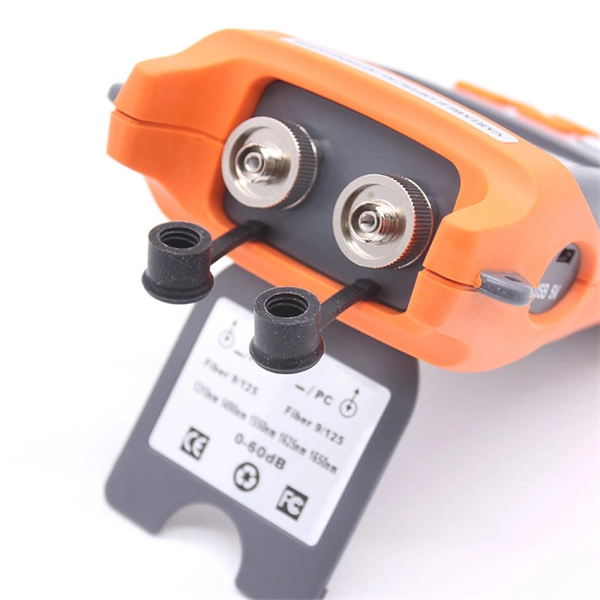
An optical time-domain reflectometer (OTDR) is an optoelectronic instrument used to characterize an optical fiber. It is the optical equivalent of an electronic time domain reflectometer which measures the impedance of the cable or transmission line under test. An OTDR injects a series of optical pulses into the fiber under test and extracts, from the same end of the fiber, light that is scatter. Reliability and quality of OTDR equipmentThe reliability and quality of an OTDR is based on its accuracy, measurement range, ability to resolve and. The common types of OTDR-like test equipment are: 1. Full-feature OTDR: 2. Hand-held OTDR and Fiber break locator: 3. RTU in RFTSs:. In the late 1990s, OTDR industry representatives and the OTDR user community developed a unique data format to store and analyze OTDR fiber data. This data was based on the specifications in GR-196, G.
[PDF]
The Base Station Optical Module Market was valued at USD 1. 2 billion in 2024 and is projected to reach USD 3. 5 billion by 2034, registering a CAGR of 11. The global market for Base Station Optical Module was valued at US$ million in the year 2024 and is projected to reach a revised size of US$ million by 2031, growing at a CAGR of %during the forecast period. It is composed of optoelectronic devices, functional circuits and optical interfaces. In this report, we will assess the current U. tariff. Base Station Optical Module by Application (Macro Base Station, Micro Base Station), by Types (Optical Receiver Module, Optical Transmitter Module, Optical Transceiver Module), by North America (United States, Canada, Mexico), by South America (Brazil, Argentina, Rest of South America), by Europe. Product Type Outlook (Revenue, USD Million, 2024 – 2034) ( Transceivers, Optical Amplifiers, Optical Switches, Others), Application Outlook (Revenue, USD Million, 2024 – 2034) ( Telecommunications, Data Centers, Enterprise Networks, Others), End-Use Outlook (Revenue, USD Million, 2024 – 2034) (. Base Station Optical Module Market report includes region like North America (U. S, Canada, Mexico), Europe (Germany, United Kingdom, France), Asia (China, Korea, Japan, India), Rest of MEA And Rest of World.
[PDF]
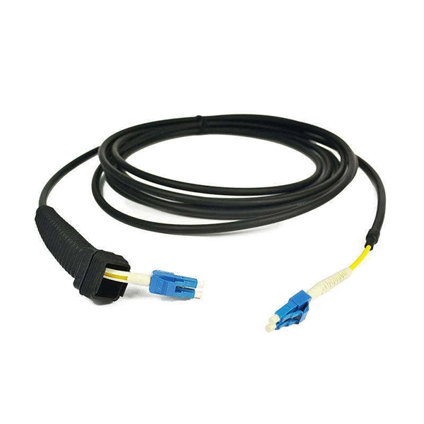
Choosing between single-mode and multi-mode optical fiber shapes the performance ceiling of every high-bandwidth industrial sensing network. This guide maps the key technical distinctions, applicable standards, and the most productive research directions for. Optical fibers are among the most transformative technologies in modern photonics, quietly enabling the global internet, precision sensing, minimally invasive medicine, and high-power industrial laser systems. The. Discover ROI-boosting fiber choices: Single Mode vs Multimode Fiber. Get the right speed & savings for your network—download our guide for free today! Understanding the physics behind Single Mode vs Multi‑Mode Fiber is essential for selecting the right conduit for any optical network. Single‑mode. Choosing single mode or multi-mode installation is unquestionably one of the most crucial decisions. Understanding the distinctions between these two kinds of fiber glass are crucial since it will have a significant impact on your network's range, bandwidth, and spending. Single mode means the. Optical fiber cable transmits data as light at speeds exceeding 100 Gbps, far surpassing the 10 Gbps capabilities of legacy Cat 6A copper cable. Additionally, optical fibers support significantly higher bandwidths over greater distances without signal degradation. While both use light to transmit data, they differ fundamentally in core structure and how light travels.
[PDF]
An optical module is a typically hot-pluggable optical transceiver used in high-bandwidth data communications applications. Optical modules typically have an electrical interface on the side that connects to the inside of the system and an optical interface on the side that connects to the outside world through a fiber optic cable. The form factor and electrical interface are often specified by an int. Electrical Interface TypesThere have been multiple variants of the electrical interface of optical modules that have been used over the years. The earliest forms of optical modules had an analog electrical interface. In the transmit dir. Many different forms of optical modulation and multiplexing have been employed in optical modules. The most common modulation technique historically has been or NRZ.
[PDF]
Use this worksheet to input values for all variables that will impact your system's performance. After entering your values, please ensure you click the 'Calculate Link Loss' button at the bottom of the page to generate your total link loss. Add connectors, splices, bends, and safety margin easily. See results instantly above the form, then adjust values. Choose a mode, then enter values and optional losses. All calculations use base-10 logarithms. mW must be greater than zero. Used only in measured attenuation mode. Length is needed. The power budget refers to the amount of fiber optic cable plant loss that a datalink (transmitter to receiver) can tolerate in order to operate properly. Sometimes the power budget has both a minimum and maximum value, which means it needs at least a minimum value of loss so that it does not. To detect whether the link runs properly, the following calculation should be performed. It is often the case to calculate the maximum signal loss across a given fiber link during optical cable installation. First, you should be aware of the fiber loss formula: The Total Link Loss = Cable. Therefore, it is very important to calculate the fiber loss and take appropriate steps. In order to get the most reliable results, an Optical Time Domain Reflectometer (OTDR) trace of the actual fiber connection should be completed. This will provide you with the real.
[PDF]