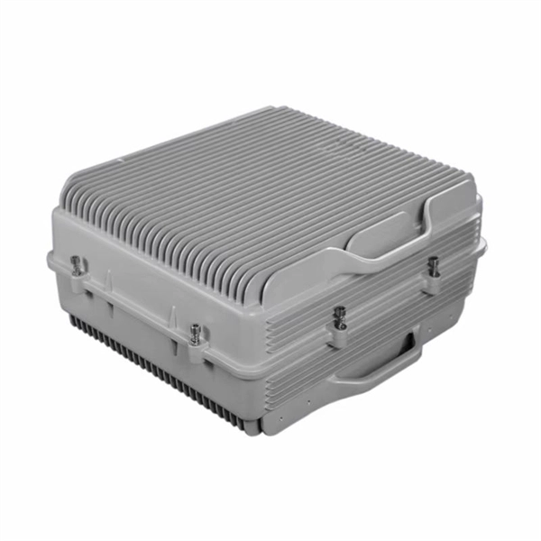
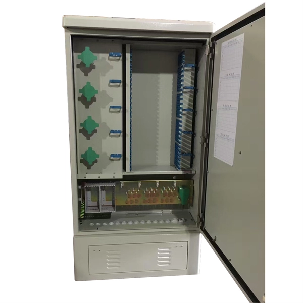
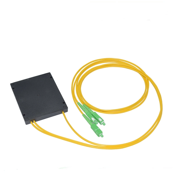
In this video, I walk you through my personal method of prepping and installing a 1:16 fiber optic splitter inside a sealed, weatherproof distribution box getting it ready for field deployment at a site. This is the way I've found to be clean, efficient, and reliable based on my experience in the. Optical splitters offer a cost-effective and dependable solution across various fiber optic applications. Also known as optical splitters, fiber splitters, or beam splitters, these devices are integrated waveguides ensuring wide bandwidth and minimal loss in high-frequency applications. They. How to install the splitter distribution box is the important information we need to know. This article includes the following: 1. Install the fixture 2. Ground the installation system 1. Have any questions? Talk with us directly using LiveChat. Fiber optic cable s transmit data using light signals, allowing for faster and more efficient data transfer compared to traditional copper cables. In the world of fiber optics, a crucial component for distributing signals is the fiber optic splitter box.
[PDF]
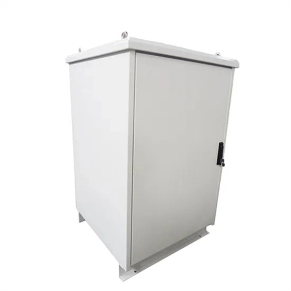
In this guide, we'll break down everything you need to know to install a distribution box correctly and confidently. Choose the right box based on environment (indoor/outdoor), load capacity, and durability. Check for proper IP/NEMA ratings and material quality. Ensure safe placement: install in. Whether you are an electrical contractor or a construction brigade, knowing how to properly and safely install distribution boxes is the basis of ensuring the safe operation of the entire system. This article details the process of installing them, which helps you comprehend distribution boxes. Electrical systems power our homes, offices, and industrial facilities, but behind every reliable electrical setup lies a crucial component that often goes unnoticed: the distribution box. This essential piece of equipment serves as the nerve center of your electrical system, managing power flow. Learn how to wire a distribution box step by step! This video shows real on-site footage of electrical installation, demonstrating safe and standardized wiring methods used by professionals. Just like travelers need clear pathways and safety protocols, your electrical circuits need proper management to prevent chaos.
[PDF]
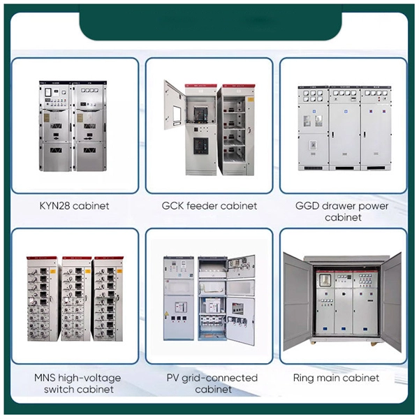
Open Frame Rack: A rack structure without doors or side panels, allowing easy access and better airflow. A data center server rack is the physical foundation of modern IT infrastructure, enabling the organized installation of servers, switches, PDUs, UPS systems, and structured cabling. There are three primary rack types - open-frame racks, enclosed cabinets, and wall-mount racks, each suited for. Understanding data center racks, chassis, and their differences is crucial for efficient server deployment. This guide clarifies common terminology confusion and design implications. Modern data center racks house multiple server chassis in standardized dimensions, enabling efficient space. IT racks are the backbone of any data center, housing critical infrastructure like servers, networking equipment, and storage devices. Whether you are designing a new setup or optimizing an existing one, understanding key IT rack terminologies is essential. This article provides an overview of the. A server rack, also known as a server cabinet, is a specialized metal frame structure designed to store and organize IT equipment. It supports hardware, enhances cooling, and ensures efficient power distribution. This guide covers everything you need for. Recommended (Suitable for all four classes; explore data center metrics in this paper for conditions outside this range. Classes A3, A4, B, and C are.
[PDF]
The International Electrotechnical Commission (IEC) provides detailed guidelines for cable tray systems under IEC 61537. This standard outlines the construction requirements, testing methods, and performance parameters for cable trays and related support systems. Cable tray (or cable ladder) systems are a popular alternative to electrical conduit systems, as they have an outstanding record for dependable service, design flexibility and cost savings in commercial and industrial applications. A properly designed and installed cable tray system will provide. maintain spacing or to keep cables in place when the tray is ect the minimum bend ra-dius for cables as they exit the bottom of the cable tray. A rung spacing of 6 to 9 inches (150 to 230 mm) is preferable when the cable tray cont d for instrumentation and control applications that require. Hubbell's NEXTFRAME® Ladder Tray is the effective and widely used cable runway that supports and delivers bundles of cable between cabinets, racks, and closets, along walls, and suspended from ceilings. The Ladder Tray features light, rugged, tubular steel construction. It is designed for. us-trations without notice. The mechanical and electrical characteristics, tests, certifications, overall quality management, recommendations mentioned. Not all cable trays are equivalent.
[PDF]
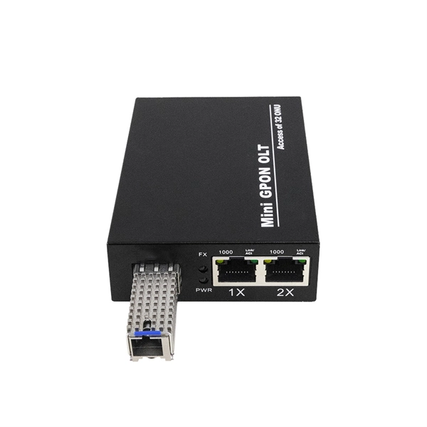
To connect copper wire cables to optical fiber cables, you need a media converter that supports 1000BASE-T. To connect an optical fiber cable to a switch, we recommend that you install a module such as a SFP (mini-GBIC) or GBIC in the switch instead of using a stand-alone media converter. Also, we. Fiber optic audio cables, also known as optical audio cables, have revolutionized the way we transmit audio signals. This cutting-edge technology offers superior sound quality, higher bandwidth capacity, and immunity to interference, making it a popular choice among audiophiles and professionals in. There are two types of SPDIF connections: coaxial and optical. Coaxial SPDIF uses an RCA connector, similar to a composite video connection, to transmit audio signals. What Is Optical? Optical. In this comprehensive guide, we'll delve into the intricacies of optical audio, walk you through the process of connecting your devices, and provide valuable insights on setting up your AV receiver for optimal performance. These light pulses travel through the cable without interference or signal. CAPS Pipeline with HDPlex Linear PSU running Win10 64 bit, AO 2. 0, RoonServer, HQPlayer -> T+A DAC8 DSD -> Linear Tube Audio's MicroZOTL2 Headphone Amp with Mojo Audio's Illuminati Linear PSU -> Focal Utopia/Audeze LCD-3 I 100% agree with your statement, however, I'm afraid the horde of.
[PDF]
This comprehensive guide will cover the step-by-step installation methodology for power-electrical bus bars, emphasizing safety measures and best practices. Bus bars play a crucial role in electrical distribution systems by providing a reliable and efficient way to conduct electricity within electrical panels. Whether in industrial, commercial, or residential applications, bus bars in electrical panels enhance power distribution, reduce wiring. Busbars are the unsung heroes of electrical panels, ensuring reliable power distribution and minimizing clutter. If you've ever wondered how to achieve a flawless busbar installation, you're in the right place. This guide will walk you through every step of the process, from selecting the right. Ever wondered how busbars, the unsung heroes of electrical distribution, are processed and installed? This article delves into the intricate steps of busbar selection, preparation, and installation, ensuring efficient and safe power distribution. You'll discover the essential tools and techniques. This prevents the parts from moving and causing a dangerous short circuit. It is a very reliable way to move energy. Most are made of copper or aluminum because these metals carry current well. The busbar shims and hardware bag in the cubicle packaging. Refer to Access to the Busbar Compartments.
[PDF]
Surge protection is very important now because new buildings have more sensitive electronics and need power all the time. Put SPDs near the main busbar. This keeps wires short. Short wires help protect devices better. Use Type 2 SPDs in most. It is very important to follow the manufacturer's installation instructions. Pay particular attention to fuse or breaker requirements and lead lengths. Failure to do so may result. Today, this article will systematically explain the wiring methods and installation specifications for surge protective devices, assisting you, Phoxinus phoxinus subsp. phoxinus, in fully leveraging the protective capabilities of a surge protection device. Protect your electrical system from power surges and lightning strikes by following this simple and clear wiring diagram for an effective SPD setup. more. Installing a whole-house surge protector is the most effective solution. Not only does it safeguard your home from power spikes, but it also helps extend the lifespan of your electronic devices and appliances. Surge protectors are crucial in safeguarding your home's electrical system and appliances. A Surge Protection Device (SPD), also called a surge protector or surge arrester, is a vital component that safeguards electrical systems and equipment from unexpected power surges. Use Type 2 SPDs in most home boxes.
[PDF]
Optical fiber cold splice technology is based on the use of mechanical connectors to join two fiber-optic cables. These connectors are designed to align and join the fibers together in a precise and secure manner. This guide covers everything: what fiber optic pigtails are, how they differ from patch cords, which connector and polish type to specify, how to choose between mechanical and fusion splicing, and the real-world applications where pigtails are the right call. The connectors used in cold. Most fibers can be mechanically stripped without the aid of chemicals or heat. The recommended cleaning solvent for connectors and tools is isopropyl alcohol (reagent grade, 99% or beter). Do not use acetone for cleaning. They directly affect insertion loss, return loss, reliability, and long-term network stability. In this guide, we break down the most common optical fiber. In this beginner-friendly guide, we'll explain what it is, why the “APC” matters, the different types you can buy, how to select the right model, and how to install and test it correctly. What is an SC/APC Fiber Optic Adapter? An SC/APC fiber optic adapter is a passive mechanical interface used to. FASTConnect® field-installable connectors are factory pre-polished connectors that completely eliminate the need for hand polishing in the field. Proven mechanical splice technology ensuring precision fiber alignment, a factory pre-cleaved fiber stub and a proprietary index-matching gel combine to.
[PDF]
Check for proper IP/NEMA ratings and material quality. Ensure safe placement: install in dry, accessible areas with good ventilation and at appropriate height (typically ~1. Practice good wiring: secure grounding, neat cable management, proper insulation, and correct wire gauge. In this guide, we'll break down everything you need to know to install a distribution box correctly and confidently. Choose the right box based on environment (indoor/outdoor), load capacity, and durability. It is usually equipped with circuit breakers, fuses, terminal connectors, and other components. It is mainly used to isolate fault circuits, prevent overload, and ensure the safe operation of. Learn how to wire a distribution box step by step! This video shows real on-site footage of electrical installation, demonstrating safe and standardized wiring methods used by professionals. Follow this guide for a clear and safe connection process: Before starting, always ensure the main power is turned off to avoid electrical shock. It serves as a central hub for distributing electricity throughout a building, ensuring that power is delivered safely and efficiently to all the required locations. Mark and Drill: Confirm the installation place (the method is above) and mark on the wall or installation surface with a marking pen. Distribution Box Installation: Put the distribution box on the.
[PDF]
At the heart of this technology lies the concept of wavelength division multiplexing (WDM), which allows multiple light signals, each at a different wavelength (or color), to travel simultaneously through a single optical fiber. Transmission loss in optical fiber varies with the wavelength of light. After continuous research and testing, scientists found that light in the 1260 nm ~ 1625 nm region has the smallest signal distortion and the lowest loss, making it the most suitable for optical fiber transmission. Figure 1. Dense wavelength division multiplexing (DWDM) originally used optical signals multiplexed within the 1550 nm band compatible with erbium doped fiber amplifiers (EDFAs), which are effective for wavelengths between approximately 1525–1565 nm (C band), or 1570–1610 nm (L band). Dense wavelength. These so-called wavelength regions—also known as optical wavelength transmission bands—are essential to modern fiber networks. This efficient use of the fiber's capacity is made possible by the. Optical fibre communication utilizes specific wavelength bands, frequently referenced by optical engineers. The values presented below are approximate and should be considered as such, as standardized values are still evolving. The article explains the fundamental principle and its.
[PDF]
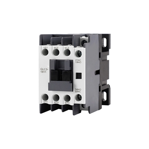
Take the appropriate rating of MCB and RCCB as per your load requirements. Identify the Input and Output sides of the MCBs and RCCBs. Connect the output of the Main MCB to the input. Primary distribution systems consist of feeders that deliver power from distribution substations to distribution transformers. A feeder usually begins with a feeder breaker at the distribution substation. Many feeders leave substation in a concrete ducts and are routed to a nearby pole. At this. Connection method: Each switch takes a wire from the incoming point and connects it to the incoming end of the switch, or uses parallel connection to reduce the difficulty of wiring. Wiring Direction: Wiring between the main circuit breaker and each branch circuit breaker in the box generally. Correct wiring methods for circuit breakers within distribution boxes are fundamental to ensuring electrical safety and compliance with established codes. The distinction between 1P and 2P circuit breakers plays a pivotal role in determining the appropriate protection level for various circuits. A primary distribution substation is the connection point of a distribution system to a trans-mission or a sub-transmission network. This guide shows you how to organize circuit breaker wiring properly. You will learn to build a safe, efficient, and professional electrical system today. Circuit breaker wiring configurations involve organizing main switches, busbars.
[PDF]