Protection is accomplished by application of a definite time overcurrent option. Current setting is greater than full load current but is lower than the motor starting current. Should a motor stall whilst running, or fail to start, due to excessive. When a motor starts, it can draw 6-8 times its full-load current for a brief period, creating significant challenges for circuit protection, voltage regulation, and system capacity planning. Understanding motor starting characteristics is essential for proper breaker sizing, motor protection relay. These time-overcurrent elements support the IEC and U. (IEEE) time-overcurrent characteristics. Electromechanical disc reset capabilities are provided for all time-overcurrent elements. protection and fault clearance in abnormal situations. The main features of the motor relay include thermal overload protection, motor start-up time supervision, locked rotor protec ion, and protection against too frequent motor starts. Addi ionally, differential protection can also be included. In order to prevent damage to the contactor, the maximum peak let-through current (Ip ) and maximum clearing energy (I2t) (amps2 seconds) of the fuse must be less than the equivalent ratings for the contactor. The clearing time and let-through characteristics of the fuse must be considered when.
[PDF]
If a fault is detected, the relay will send signals to adjacent relays and circuit breakers, allowing the closest breaker to trip first while other breakers delay their operation. This selective coordination helps isolate the faulted zone while maintaining the power supply to the. A protection relay is a crucial component of electrical systems that safeguard infrastructure, employees, and equipment from electric problems and malfunctions. It functions as a watchdog by constantly surveying multiple system components including voltage, current, frequency, and phase angle. It. A protective relay is the vigilant guardian of electrical networks, constantly monitoring and analyzing electrical parameters to detect abnormal events. Acting as the first line of defence, it swiftly detects faults, such as short circuits or overcurrents. It triggers protective actions to isolate. In electrical engineering, a protective relay is a relay device designed to trip a circuit breaker when a fault is detected. : 4 The first protective relays were electromagnetic devices, relying on coils operating on moving parts to provide detection of abnormal operating conditions such as. A protective relay is an intelligent device that senses abnormal electrical conditions, such as overcurrent, under-voltage, or frequency deviations. It initiates the operation of circuit breakers to isolate the affected section.
[PDF]

An analog accessory for use in a system for testing protection relays is provided, comprising inputs connectable to the current outputs of a test-set for protection relays and voltage outputs connectable to a protection relay to be tested. The register contains national patents and information related to European Patents validated in Malta. It currently provides European patent numbers, filing dates, titles, abstracts, classifications, applicants, bibliographic data, status, priorities, expirations, annuity/renewal fees. The utility model discloses a power plant relay protection tester, belonging to the technical field of relay protection testers, which comprises a relay protection tester body and a shell for placing the relay protection tester body, wherein a partition plate is arranged in the shell, a driving. Application to amend a patent application or registration. Convert a European patent application to a National patent. Request an extension of a time limit for the submission of patent documents. By providing an electric circuit adapted to convert current. Background Relays and metering are an important part of power generation, power transmission, and power con- sumption in electric power systems and the power grid. Relays provide monitoring and protection of equipment and personnel.
[PDF]

A protection relay tripping circuit connects relays to breakers for fast fault isolation. Key components include trip/close coils and anti-pumping relays. Proper design, testing, and maintenance ensure reliable overcurrent, differential, and auto-reclosing protection in power. The protection relay tripping circuit refers to the critical electrical control loop that executes trip/close commands from protective relays to circuit breakers, ensuring rapid fault isolation in power systems. Essential. Electromechanical protective relays at a hydroelectric generating plant. The relays are in round glass cases. In electrical engineering, a protective relay is a relay device. A protective relay is an intelligent electrical device designed to detect faults in power systems and initiate corrective actions such as tripping a circuit breaker. Its main purpose is to safeguard electrical equipment like transformers, generators, and transmission lines from damage due to. By definition, a protective relay is a switchgear device that detects faults and initiates the circuit breaker operation to isolate the problematic component of the system. Electrical values are measured by these relays to determine abnormal circumferences of a circuit. It functions as a watchdog by constantly surveying multiple system components including voltage, current, frequency, and phase angle.
[PDF]
At AES Power Solutions, we provide comprehensive lightning protection solutions engineered to shield your infrastructure, equipment, and personnel from the dangers of lightning strikes and electrical surges. An essential electrical component for properly distributing electricity to lighting systems in dangerous areas with explosive gasses, vapors, or combustible dust is the Explosion Proof Lighting Distribution Box. It is extensively utilized in sectors where stringent safety regulations are. BXM (D)8050 Series Explosion Proof. ◆ The explosion-proof illumination distribution boxes is equiped with compound design: Combines flameproof (Ex d) and increased safety (Ex e) chambers for flexible protection. Our LPS products include: Lightning rods: Also known as air terminals, these are metal rods placed at the highest point of a structure. Grounding systems: These provide a. Our robust distribution boxes are engineered to provide efficient and reliable power management for a wide range of applications. Designed with high-quality materials and advanced safety features, these distribution boxes ensure the safe and organized distribution of electrical power in. 1This is a technical guideline for the purposes for carrying out remediation. It is therefore RSC's Standard. The RSC adopted the technical guidelines from local and international technical Standards and international best practices. The Building Standard developed by the.
[PDF]

The total interruption time for a modern high-voltage SF6 circuit breaker is typically between 40 to 60 milliseconds on a 50Hz grid, or 2 to 3 cycles. This is the total time from the trip signal to the final arc extinction, a critical parameter for grid safety. While knowing the total time is a. When a SF6 circuit breaker (CB) hits its critical low pressure, its fault interrupting capability can be compromised. Most TOs protect against this by either auto-opening the CB prior to reaching the critical low-pressure level or by blocking the CB from tripping (when it reaches the critical. The protected zone is defined and limited by different things depending on the protection function. Definite time delay means that the protection operate time dose not change or depend on the fault type or the fault current magnitude. Instead of oil, air, or a vacuum, a sulfur hexafluoride circuit breaker uses sulfur hexafluoride (SF 6) gas to cool and quench the. Page 1 Content Instruction Manual circuit- breaker GL317 With spring operating mechanisms FK3- 4 Administrator First issue Compiled by Approved by 19- 11- 2012 J. Texier Imagination at work Grid Solutions 04- 2017 D1736EN/03 GE Information 1/10. Page 2 Content Instruction Manual This. A comparison of the time it takes protective devices to operate when certain levels of normal or abnormal current pass through them. LV circuit breaker ratings.
[PDF]

The standard industry practice is to set overload relays at 125% of the motor's nameplate Full Load Ampere (FLA) rating. Plug Setting Multiplier (PSM) indicates how many times the determined relay secondary current (typically the CT secondary) exceeds the relay pickup (plug) current. It is the key quantity utilized in IDMT (inverse definite minimum time) curves to calculate the basic operating time. PSM (Plug Setting. An overload relay is a crucial device for motor control, designed to prevent motors from overheating or suffering winding damage due to excessive current. Motor overload relays protect against sustained overcurrent conditions that cause dangerous overheating, insulation breakdown, and premature. Overload relays protect motors and equipment from thermal damage caused by prolonged overcurrent conditions. IEC 60255 defines standards, formulas, and performance requirements, enabling accurate calculations and real-world applications. How is the overload relay current calculated? Why include. Setting motor overload relays correctly is critical for protecting AC induction motors from sustained overcurrent conditions while avoiding nuisance trips during normal starting transients. This occurred when the relay F was set at 1. The complaint was that the relay tripped instantly on overload when the thermal damage curve show plotted for a specific current that was less t an.
[PDF]
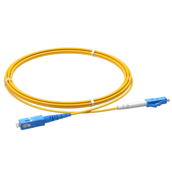
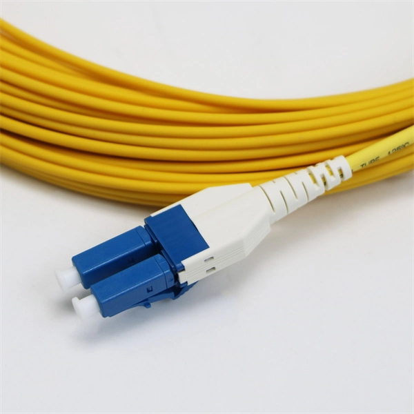
Temukan daftar Supplier, Pabrik, Importir, Distributor dan Toko Kabel Patch Cord untuk wilayah Indonesia . Update setiap hari, harga kompetitif dan layanan terpercaya. High performance and high quality connectors cable assembly are required for next generation optical networks to assure long term reliability for demanding applications such as FTTx, DWDM, 100G, CATV and etc. The connector assemblies are IEC, Telcordia and RoHS compliant. The termination passed. Prima Akses Digital Indonesia, is a Indonesian local company specialized in fiber optic product development and solution service for network infrastructure. Prima Akses Digital Indonesia, established in 2020, is supported by several partner companies and management which have been experienced in.
[PDF]

The SEL-221F Relay uses positive-sequence memory voltage polarized mho distance elements for phase and ground distance protection. These elements expand in proportion to the source impedance to provide more resistive fault coverage than self-polarized mho elements. VAMP 221 arc protection system components. Central unit VAMP 221. I/O units VAM 12L / VAM 12 LD, VAM 10L / VAM 10LD, VAM 3L / VAM 3LX and VAM 4C / VAM 4CRL / VAM 4CD 10 1. Arc sensors VA 1 DA, VA 1 EH, ARC SLx. Schneider Electric VAMP range is an arc flash detection and protection pioneer offering fast and reliable devices to improve safety. VAMP 221 significantly reduces the risk of potential personal damage, and material and production losses caused by arc fault. VAMP 221 complies with the latest standards concerning the. Serial communications ports allow local or remote interaction with the relay. 5” high chassis sizes. The report will identify methodology behind these practices, present issues raised by the integration of microprocessor relays and the internal logic and external communication configurations, ying. In the design of electrical power systems, the ANSI Standard Device Numbers denote what features a protective device supports (such as a relay or circuit breaker).
[PDF]
What is the cost of a relay coordination study in Singapore ? The cost of a protective device study in Singapore depends on the complexity of the electrical system, facility size, and number of relays. I2R, as a firm of Professional Engineers and Licensed Electrical Workers, is qualified under the Electricity Act to carry out all types of electrical testing and commissioning works to ensure that electrical apparatus are fit for power energization and safe for use and operation. We have all the. We are Specialized in Low Voltage Switchgears Testing, Commissioning, Maintenance and Installations from OEM's. We do factory Acceptance and Site Acceptance Testing and Commissioning support of LV Switchgears. Earth loop impedance measurments. Care Offers cost-effective solutions for protective device coordination in compliance with. Advance Engineering and Testing (AET) Pte Ltd established on 2019, is a top provider of electrical testing ranging from commercial, domestic, and industrial. The company provides 24/7 onsite support with prioritization of customer satisfaction. Their vision and mission statement is to continuously. The type of testing required for each specific relay needs to be designed with the goal of accomplishing the objective. We perform testing in four specific classes which. Our services are applicable to a number of industries such as Petrochemical industries, Oil and gas fabrication industries, Wafer fabrication plants, Pharmaceuticals.
[PDF]

In this guide, we'll explore what protection relays are, how they're classified, the types available, and how they work with instrument transformers to create secure zones of protection. What Is a Protection Relay?. Protective Relay Definition: A protective relay is an automatic device that senses abnormal conditions in electrical circuits and triggers actions to isolate faults. Types of Protective Relays: Protective relays are categorized by their mechanism (electromagnetic, static, mechanical) and function. This article covers various types of protective relays, such as overcurrent, directional, and differential relays, highlighting their operating characteristics and applications in electrical systems. They don't just protect equipment; they ensure safety, prevent downtime, and save lives. A protective relay is a device that detects the fault and initiates the operation of the circuit breaker to isolate the defective element from the rest of the. The rectangular devices are test connection blocks, used for testing and isolation of instrument transformer circuits.
[PDF]
The relay block comprises the two protection units, phase protection unit and earth protection unit. When the value of the current in any of the phases is greater than the pick up value, the phase protecti.
[PDF]
Specifically designed for settings-based protection testing with a high degree of automation, our modular software Test Universe offers numerous functions and application-optimized test modules that save yo.
[PDF]
Protection: CVTs supply voltage signals to protective relays, enabling them to detect faults and initiate appropriate actions, such as circuit breaker tripping. Control: CVTs can also be used in control systems to monitor voltage levels and provide feedback for voltage regulation. Capacitive Voltage Transformers (CVTs) are common in high-vo tage transmission line applications. These same applications require fast, yet secure protection. However, as the requirement for faster protective relays grows T models whose purpose is to identify which major CVT components contribute. ve Voltage (CVT) and Capacitance Coupled Voltage Transformers (CCVT). With this comprehensive range of accurate power sensing devices coupled with GE's vertical integration approach and skilled design engineering staf, we work closely with our globa ems for applications ranging from high-voltage to. Capacitive Voltage Transformers (CVTs), also known as capacitor voltage transformers, are essential components in high-voltage power systems. They provide a cost-effective and reliable means of measuring voltage and supplying power to protective relays and metering equipment. This essay will delve. Potential transformers and coupling capacitor voltage transformers (CCVT's) have been used successfully for providing voltage to the inputs of meters and relays since the 1960's. It utilizes a capacitive voltage divider in conjunction with an electromagnetic voltage converter to provide a.
[PDF]
of relay protection coordination for a PV power plant connected to the distribution network is presented. In recent years, installation of PV power plants in the distribution network has increased significantly. I.
[PDF]