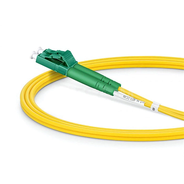
It supports multi-mode fiber with a reach of 300m via a duplex LC connector. Designed for extended temperatures (-40°C to 85°C), it includes Digital Optical Monitoring (DOM) and guarantees full compatibility with H3C equipment, making it ideal for harsh environment deployments. Optical modules transmit signals over optical fibers. Optical transmission features low loss and is fit for long distance transmission. The. Max. Note: Due to DigiKey value-add services the packaging type may change when product is purchased at quantities beneath the standard package. Buy now, ships today. SFP-XG-SX-MM850-D-C - Transceiver Module Networking and Communications 10Gbps 850nm LC Duplex Pluggable, SFP+ from ATGBICS. View. This H3C® SFP-XG-SX-MM850-A compatible SFP+ transceiver provides 10GBase-SR throughput up to 300m over multi-mode fiber (MMF) using a wavelength of 850nm via an LC connector. Our transceiver is built to meet or exceed OEM specifications and is guaranteed to be 100% compatible with H3C®. With a data rate of 10. This transceiver is compliant with SFF-8431, SFF-8432 and IEEE 802. 3ae standards and for seamless interoperability in multivendor environments.
[PDF]
Huawei QSFP-40G-LR4 40GBASE-LR4 QSFP+ optical module, 40G single-mode up to 10km via LC duplex for Huawei 40G switches. Request live stock & price. Targeting network engineers and IT procurement specialists, this module ensures high-speed, long-distance data transmission with reliable performance. The 40G QSFP+ LR4 is a transceiver module designed for 10km optical communication applications. The design is compliant with 40GBASE-LR4 of the IEEEP802. The module converts 4 inputs channels (ch) of 10Gb/s electrical data to 4 optical signals and multiplexes them into a single channel. Sorry, it doesn't seem to be a valid email address. The Huawei 40G Base-LR4 Optical Transceiver, QSFP+, 40G, Single-mode Module (1,310 nm, 10 km, LC) is guaranteed 100% Compatible and Functional in its intended equipments.
[PDF]
These modules are engineered with high-grade components designed to withstand the vibrations of washboard forest service roads and the temperature swings of high-altitude passes. 00 Original price was: $46. Activates High current relay when High Beams are turned on, used to add large light bars and driving lights without having to install additional switches in the dash. Plugs directly into Polaris Pulse System for switch lighting and keyed on ignition. The CanM8 Cannect Duo (Speed Pulse & High Beam) Interface is a 2-output CAN Bus interface which provides a quick solution for detecting high beam activity on vehicles which feature CAN Bus wiring. The Cannect Duo Interface also features a square pulsed speed signal output from the vehicle at a. Electronic technology has advanced so that an electronic control unit (ECU) is required to control the functions of full LED automotive headlights. An ECU consists of mainly LED drivers for headlight functions such as high beams, low beams, daytime running lights, position lights, turn indicators. This module resolves the issues with the headlight turning off, or flashing after the ignition is turned on. This issue is mainly affecting Chrysler, Jeep, Dodge vehicles, but some other modern cars will have this same issue. They offer a true plug-and-play experience, effectively eliminating the common flickering issues associated with.
[PDF]
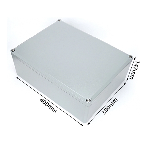
Optical trap or "tweezers" is a device used to apply piconewton sized forces and make precise measurements on a scale of roughly one micron. It can be created by applying a precisely focused laser onto a dielectric material. Thorlabs' OTKB (/M) Modular Optical Tweezers provide users with a tool for trapping and manipulating microscopic-sized objects. These laser-based tweezers, or traps, have been employed in numerous biological experiments. Biological applications for optical tweezers include trapping viruses and. Our advanced optical trap generator based on ultra-fast AOD technology. Versatile and flexible optical trap manipulation designed for biological samples. Learn to calibrate the 20. Use calibration information to observe the rotation of E. coli bacteria, and determine the forces required to stop this rotation. Based on their design, Thorlabs has collaborated with the aforementioned authors to design an OTKB optical trapping kit that includes all necessary components and provides the same capabilities. Enclosed into a high-quality aluminum box and assembled onto the. Torr Scientific offers a range of magneto-optical traps (MOT) (also known as atom trap chambers) used as part of ultra-cold vacuum systems, to capture atoms for testing purposes. This is a chamber module, formed of low-magnetic permeability materials for use at ultra-low temperatures nearing.
[PDF]
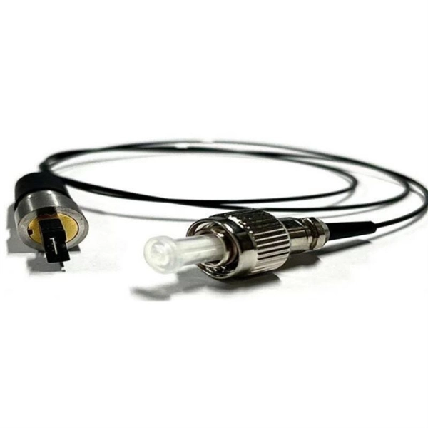
As illustrated in typical SFP internal structure diagrams, the module's core components include an optical transmitter assembly (TOSA), laser driver, optical receiver assembly (ROSA)—some high-sensitivity modules (like L16. 2) use APD receivers, which require an additional booster. As a key element in optical communication systems, optical transceivers serve as media between network devices to transmit and receive data. There has been lots of articles and guides on transceiver modules in the perspective of the package type while only a few of them cover the internal elements. Optical modules are devices used to connect network devices, transmit and receive data between network devices, and can be used to convert optical and electrical signals. The optical module is a very important component in an optical communication system. When you remove the metal housing of the optical transceiver, you will find that the internal components are connected to each other. The following section will focus on. In the era of 5G, AI, and high-speed data centers, optical modules serve as the core bridge for converting electrical signals to optical signals (and vice versa), enabling fast, reliable data transmission across networks. Among various optical module form factors, SFP (Small Form-Factor Pluggable). The optical transceiver module is mainly composed of three parts: housing, optical device and integrated circuit board. The following section will focus on.
[PDF]
The CFP standard defines a pluggable optical transceiver form factor capable of supporting 40G and 100G Ethernet, OTN (Optical Transport Network), and SONET/SDH protocols. The acronym "CFP" represents the Roman numeral "C" (100), aligning it with 100 Gigabit Ethernet. Originally introduced as the first standardized pluggable solution for 100 Gigabit Ethernet, CFP (C Form-factor Pluggable) modules were engineered to support high-bandwidth, long-distance transmission using multiple optical lanes. Their robust design made them ideal for carrier-grade networks, DWDM. The C form-factor pluggable (CFP, 100G form factor pluggable, where C is Latin: centum "hundred") is a multi-source agreement to produce a common form-factor for the transmission of high-speed digital signals. Developed collaboratively. The CFP optical transceiver module is a standardized, hot-swappable optical transceiver used for high-speed data transmission in telecommunications and data center networks. CFP transceivers are defined by CFP MSA to enable 40 Gb/s, 100 Gb/s and 400 Gb/s applications. It features a new concept known as. This article breaks down the key differences between CFP, CFP2, CFP4, and CFP8 optical transceivers commonly used in fiber optic networks. Figure 1: Dimensions of CFP, CFP2, CFP4, and CFP8 The table below summarizes the specifications of each form factor: 24 W (Max. ) In essence, the progression.
[PDF]
The Huawei OEGD01N01 is an Optical Functional Module known for its robust functionality in networking environments. It is a 1000BASE-T-SFP Module featuring an RJ45 Electrical Module with auto-negotiation capabilities. Optical modules are widely used in switches, network interface cards (NICs), routers, and other communication devices. During use, reading optical module information helps understand its real-time operating status, enabling faster troubleshooting of link abnormalities. The following uses the. A switch must use optical or copper modules that have been certified for use on Huawei switches. Non-certified optical or copper modules cannot ensure transmission reliability and may affect service stability. Designed for optimal performance, it supports a longest transmission distance of. OLT is the world's first Terabit fiber access system. With the pending support for XG-PON1 (10Gbps downstream and 2. 5Gbps upstream data rates) technology, Huawei's MA5600T OLT is designed to provide even higher subscriber bandwidth in shared fiber splitter applications. Huawei's all-in-one fiber. TX/RX power test ensures that the optical power are within the thresholds; remove the aged optical module with power loss, and the fake module with counterfeit label. Huawei is not liable for any problem caused by the use of non-certified optical or.
[PDF]
In this Cisco Tech Talk, learn how to view the optical module status on a Cisco switch using the Command Line Interface (CLI). This video demonstrates how to access the optical module status, check for any issues, and monitor the health of your network's optical components. Learn. When optical modules operate on a switch, it is usually necessary to read the module's internal information to understand its working status—such as connection status and real-time metrics like optical power and temperature. Additionally, identifying module information helps detect coding. This chapter describes how to configure the Optical Amplifier Module and Protection Switching Module (PSM). When you plan to replace a configured optical module with a different type of optical module, you must clear the configurations of the old module before you install the new module. By checking module health, compatibility, and digital diagnostics, you can quickly confirm correct installation, detect optical problems, and maintain accurate hardware. Small Form-factor Pluggable modules (SFP module) are the workhorses of modern network connectivity, enabling flexible fiber optic or copper links between switches, routers, firewalls, and servers. Whether you're upgrading bandwidth, replacing a faulty unit, or reconfiguring your topology, knowing.
[PDF]
Quick Answer: To check CPU utilization on a Cisco switch, use the command “show processes cpu” in the CLI. This displays current CPU load, CPU usage history, and process-specific details, aiding in network performance troubleshooting. The CPU becomes too busy when either an IOS process consumes too much CPU time or the CPU receives too many packets from the switching hardware. When either of these two CPU consumers requires the CPU resource to the detriment of the other, then the CPU is too busy. For instance the CPU is. High CPU utilization on Cisco switches can lead to degraded network performance, packet loss, and even switch failures. Identifying and troubleshooting the root cause of high CPU usage is essential for maintaining a healthy network. In this article. I noticed that after having VLANs, ClearPass, spanning tree, and all other settings configured, that CPU util was just sitting at or above 85% on all these switches. I updated firmware to the latest version on all of them, but that didn't help. Problem analysis process 1. According to the switch logs, after searching for related processes, we can find that the. my switch core has high CPU usage every 3 minutes, switch logs attached. Do the outages/CPU spikes occur at the same time as the log entries appear such as : 00828 lldp:. Thank you, Fix the problem indicated.
[PDF]
The base station can be divided into two modules: the RRU for transmitting signals and the BBU for processing signals. The BBU is small and exquisite, with low power consumption, while the RRU is large and has high power consumption. Which optical modules are commonly used in 4G base stations? In this blog, ETU-LINK will talk about 4G base stations and common types of optical modules. The BBU is small and. In a mobile communication base station, the antenna is at the top of the signal tower, and under the tower is the machine room, in which the base station is placed. Generally, the. RRU and BBU are crucial components in base station construction, enabling a distributed architecture that improves efficiency and reliability. Here's a breakdown of each: The central processing unit in a base station. Handles baseband signal processing, transmission scheduling, and network interfacing. BBU is used for signal processing, RRU is used for signal transmission and reception, and the feeder is used to connect the antenna and the base. The base station is logically divided into two parts: BBU and RRU. RRU is responsible for signal transmission and reception, and BBU is responsible for signal processing. The feeder is used to connect the antenna and the base station, and the supporting equipment is mainly the power supply and air.
[PDF]
The main trade show for the large optical module industry is the Optical Fiber Conference (OFC), that is held annually in southern California. Other prominent shows for the industry include ECOC in Europe and FOE in Japan.
[PDF]
Huawei OLT Comparison: MA5600T vs MA5800 vs EA5800. This guide explains the architectural differences, PON technologies (GPON, XGS-PON), and helps you choose the right OLT for FTTx networks. MA5603T is multi service based while MA5683T is just OLT, MA5603T can support service like ADSL, VDSL, GPON etc, while MA5683T only supports GPON, P2P etc, but their hardware and configuration command is the same. MA5683T vs MA5680T? The only difference is capacity, MA5683T max support 6 service. Hi, This is ISP-Home. com, we excel in delivering high-performance fiber optical products, connecting you to a world of precision and reliability. As optical fiber access nodes keep moving closer to end users, OLTs are closer to end users. Deployment scenarios are complex and diversified. In this case, network needs OLTs with small volume and low density. The MA5801 series OLT is a compact and. When selecting a Huawei OLT (Optical Line Terminal), prioritize models that support your required number of subscribers, offer scalable GPON or XGS-PON technology, and integrate seamlessly with existing Huawei ONTs. For most mid-sized service providers, the MA5600T or MA5800-X17 provides the best. OLT Series: Access product manuals, HedEx documents, product images and visio stencils. The MA5800 is the industry's first smart aggregation OLT with a distributed architecture. It is positioned as the next-generation OLT for NG-PON.
[PDF]
Check the diagnostic information, which shows that the received optical power is low, with a threshold of -3 to -23. 01, currently at -22. Once it exceeds the threshold, an alarm will be triggered. Troubleshoot the link, and if the link is normal, replace the optical. Run the display interface transceiver verbose command in the user view to check whether the transmit optical power (Tx Power) of the interface is within the allowed range. If yes, collect alarm, log, and configuration information, and contact technical support personnel. If the optical module is. An optical module was faulty. Cause 2: Output Optical Power Too High. Services on the optical module may be affected, which may cause bit errors, error packets, or even service interruption. During use, reading optical module information helps understand its real-time operating status, enabling faster troubleshooting of link abnormalities. The following uses the. The International Photonics & Electronics Committee (IPEC) is an international standards organization that is committed to developing open optoelectronic standards and delivering strategic roadmap reports. IPEC focuses on standardizing solutions in optical chips, optical/electrical components, and. The optical module on the port generates an alarm. Often referred as I²C, I2C, IIC (Inter-Integrated Circuit), MDIO (Management Data Input/Output) or CMIS (Common Management Interface Specification), these serial bus.
[PDF]
Gigabit is a decimal unit defined as per SI standard. 1 Gigabit = 1000 Megabits. The unit symbol for Gigabit is Gbit or Gb. Abbreviated as Gb, a gigabit is a method of measuring data transmission. When the "b" is uppercase, like GB, this refers to a gigabyte. What comes before a gigabit? What comes after a gigabit? Gigabit vs. other data measurements. What comes before a. Gigabit single-mode fiber optic module Common parameters of optical modules 1. Center wavelength 1) 850nm (MM, multi-mode, low cost, but short transmission distance, usually only 500M); 2) 1310nm (SM, single mode, large loss during transmission, small dispersion, generally used for transmission. In computer networking, Gigabit Ethernet (GbE or 1 GigE) is the transmission of Ethernet frames at a rate of a gigabit per second. The most popular variant, 1000BASE-T, is defined by the IEEE 802. It came into use in 1999 and has replaced Fast Ethernet in wired local networks due to. What is 1 Gig in Mbps? 1 Gigabit (Gb) is equal to 1000 Megabits (Mb). This conversion is important to understand because data transfer rates are commonly measured in Mbps, but many internet plans, network devices, and even transceivers are rated in Gbps. So. A gigabit (Gb) is a unit of digital information equal to 109 bits, or 1,000,000,000 bits. It uses the standard SI decimal prefix 'giga-'. It is important to distinguish.
[PDF]
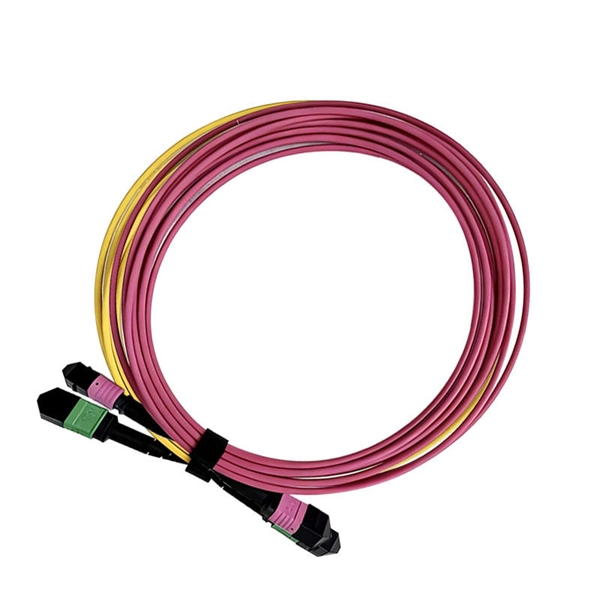
This guide breaks down practical differences—core geometry, wavelengths, connector types, performance limits, cost trade-offs, and ideal use-cases—so you can pick the right optical modules with confidence. SFP (Small Form-factor Pluggable) is a compact, hot-swappable module used in network devices such as switches, routers, and servers to provide network connectivity and is widely used in network communications. By using different interfaces and single-mode or multimode fiber depending on the. Multimode and Singlemode optical modules differ in terms of fiber type, transmission distance, cost, and application scenarios. Understanding these differences is the first step in selecting the right module. Multimode Optical Modules: These modules are typically used for shorter transmission. Multimode SFP module offers a practical solution for short- to medium-range 100G transmissions, particularly in high-density environments where performance, compatibility, and cost control are equally critical. At the end of the day, they answer one simple question: How much bandwidth can this fiber handle, and how far can it go? “OM” stands for Optical Multimode, which is a classification system for multimode fiber.
[PDF]