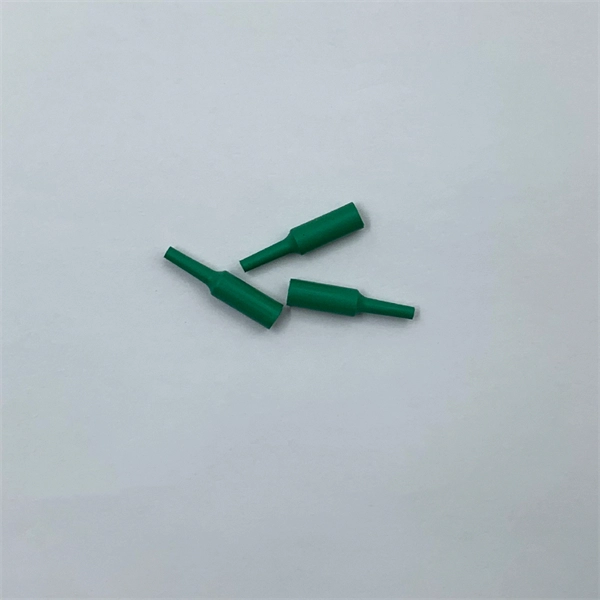
Learn how to set up, calibrate, and use the FS-V11, a versatile sensor with automatic and manual calibration options, plus expansion unit compatibility. It's designed to work with various fiber optic cables and can be easily set up and calibrated with a range of options for sensitivity. Digital Optical Fiber Amplifier Sensor FV-V11 Photoelectric Sensor NPN NO or NC (Selectable via Button), 12 to 24V DC Supply Voltage, Red LED, FINE (250 µs), TURBO (500 µs), and SUPER TURBO (1 ms) Response Time, LIGHT-ON/DARK-ON (switch-selectable) Operation Modes, Digital LED monitor with seven. PNP open-collector 100 mA max. ), Residual voltage: 1 V max. Incandescent lamp: 10,000 lux max. *1 If more than one unit is used together, the ambient temperature varies with the conditions below. Mount the units on the DIN rail with mounting brackets and. Owner's manuals and user's guides for Sensors Keyence FS-V11 (P). Keyence FS-V11 (P) user manuals PDF. Browse online or download Sensors Keyence FS-V11 (P) User Manual. The orange LED is normally part of the bar graph LED monitor. It is used as a calibration indicator during the setting of the sensitivity. To connect several units, be sure to mount. Since 1996, the FS-V Series has utilised a parallel processing chip rather than a general-purpose CPU. This chip is designed especially for fi breoptic sensors in order to offer accelerated data processing and specialisation.
[PDF]
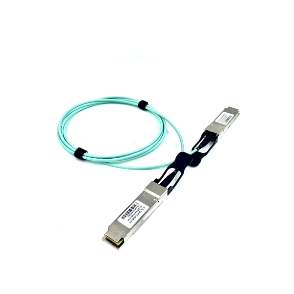
Learn how to extend GDB with optical signal breakpoints for efficient photonics chip debugging and testing with practical implementation steps. Debugging photonics chips requires specialized tools that can monitor and analyze optical signals alongside electronic ones. Legal status (The legal status is an assumption and is not a legal conclusion. Google has not performed a legal analysis and makes no representation as to the accuracy of the status listed. ) Current Assignee (The listed assignees may be inaccurate. These modules leverage advanced signal processing, modulation, and high-speed interfaces to provide high bandwidth, low latency, and reliable performance. Standard debugging tools like. modules used with NADDOD switches, for reference by technicians and users. For any questions, please contact NADDOD. When testing PRBS, there are 3 test nodes: MAC ----> PHY. In view of this, the embodiments of the present invention expect to provide an optical module commissioning device, commissioning method, and electronic equipment to solve the time-consuming technical problem of manually commissioning a DSFP optical module through a commissioning device in. Optical detection chips serve as essential components in intelligent optical computing systems, demonstrating crucial significance. These chips exhibit high sensitivity and broad wavelength response ranges, enabling precise optical signal reception and conversion while providing reliable data input.
[PDF]
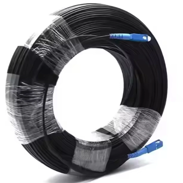
Raman amplification is a way of increasing the signal strength in an optical fiber. It is often used in a fiber that carries a signal for a long distance (such as in an undersea cable). Technically, it works by stimulating, in which a lower frequency 'signal' induces of a higher-frequency 'pump' photon in an optical medium in the nonlinear regime. As a result, another 'signal' photon is produced, with the surplus energy resonantly passed to the vibrational states of the.
[PDF]
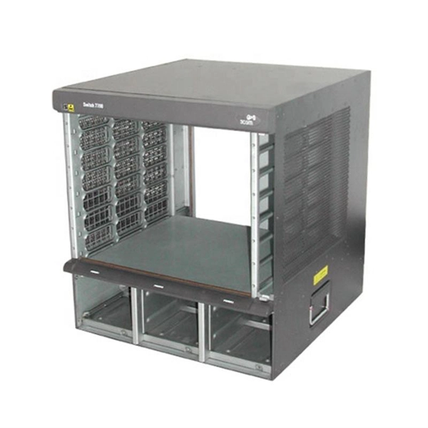
This video shows real on-site footage of electrical installation, demonstrating safe and standardized wiring methods used by professionals. more Learn how to wire a distribution box step by step! This video shows real on-site footage of. Hey, in this article we are going to see the Single Phase Distribution Box Wiring Diagram and Connection Procedure. A distribution board or distribution box is where the main power supply is distributed to multiple loads. And all the switching and protective devices are installed in the. Box installation: Make sure that Distribution box has been correctly installed and fixed. Material preparation: Prepare the required circuit breakers, wires, wiring ties and other materials, and ensure that they meet the design drawings and installation requirements. Location determination:. In this video, we'll walk you through the process of wiring a home distribution box with a detailed connection diagram. Whether you're an electrician or a DIY enthusiast, this guide will help you understand the basics of home electrical distribution. What Is a Distribution Box? A distribution box, also known as an electrical distribution board, is a critical component in electrical systems. It serves as a.
[PDF]