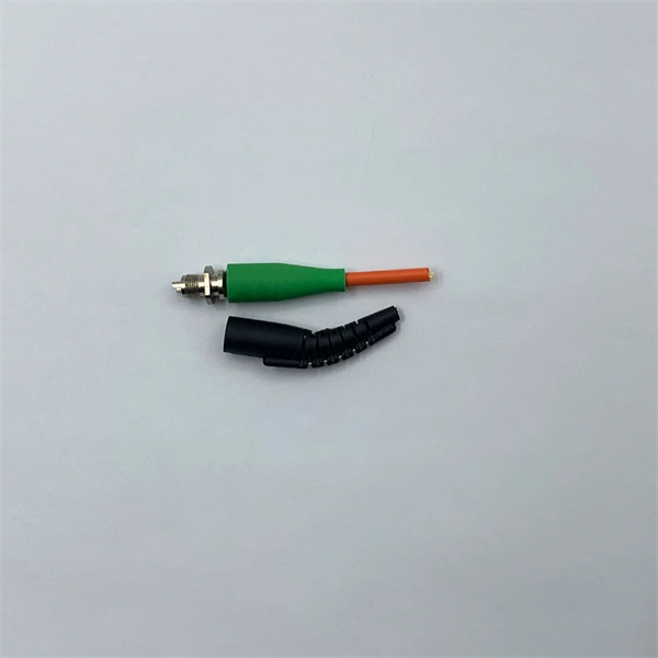
Even when splicing identical fibers together, if they are not perfectly aligned, optical power will be lost and attenuation across the splice will exist. The performance of a fiber optic splice is determined by a number of factors, including the quality of the fiber, the cleanliness of the splice, and the techniques used to make the splice. Intrinsic factors, such as the refractive index of the fiber, are those that are inherent to the fiber itself. Fiber optic cable splicing is the process of joining two fibers end-to-end to create a continuous optical path. In PON and FTTx networks (e., FTTH, FTTP, FTTM), splicing is essential for extending cables, repairing breaks, or connecting backbone and distribution lines. To protect these vulnerable. Fiber loss, also called fiber optic attenuation or attenuation loss, refers to the loss of signal between input and output. Losses can be introduced by various means such as intrinsic material absorption, scattering, bending, connector loss and more. The absorption is caused by the absorption of the light and conversion to heat by molecules in the glass. Primary absorbers are residual OH+ and dopants used to modify the refractive index of the glass. Unlike using connectors, which are designed for frequent connection and disconnection at patch panels, splicing creates a permanent, stable joint with minimal light loss. This process is fundamental to building and.
[PDF]
When a long-distance module transmits signals over relatively short distances—or when the receiver is too close to the transmitter—the intense optical signal may directly saturate the receiver's optical detector. Optical Modules (also known as Optical Transceivers) are critical components in fiber optic communication systems. As the core optoelectronic devices operating at the Physical Layer of the OSI model, their primary function is to perform electro-optical and photo-electric conversion during signal. As an essential component of optical fiber communication, optical modules are optoelectronic devices that facilitate the conversion between optical and electrical signals during the transmission process. This is not an arbitrary adjustment but a necessary measure, carefully implemented based on signal transmission principles, device specifications, and practical. Optical Signal Attenuation is the single greatest factor limiting the distance and performance of your network. Understanding it is crucial for anyone involved in data centers, telecommunications, or enterprise networking. This guide will demystify signal loss, explore its causes, and show you how. In the field of optical fiber communication, the attenuation operation of long-distance modules is one of the key links to ensure the stable operation of the communication system. This operation is not carried out arbitrarily, but is a necessary measure after comprehensive consideration of many.
[PDF]
Low Attenuation: G655 fibers have low signal loss over long distances due to their low attenuation coefficient. This allows for efficient transmission without significant degradation or amplification requirements. This Recommendation describes the geometrical, mechanical, and transmission attributes of a single-mode optical fibre which has the absolute value of the chromatic dispersion coefficient greater than some non-zero value throughout the wavelength range from 1530 nm to 1565 nm. This dispersion. This specification covers Optical Ground Wire Cables (OPGW) for the installation on high voltage overhead power lines. The cable contains optical fibers for data transmission and telecom purposes and is installed instead of a ground wire. The specification describes the basic design of an. G. 657 are ITU-T standardized singlemode fiber types used across long-haul, metro, ODN, and FTTH networks. Each fiber type is engineered with different refractive index profiles, dispersion properties, and bending performance to support specific applications—from long-distance. The optical fibres are made of a high grade doped silica core surrounded by a silica cladding; they are coated with a dual layer of UV cured acrylate based coating. This single mode fibre supports high-power signals and longer distances, as well as closely spaced DWDM (dense WDM) channels at rates.
[PDF]
Attenuation in fiber optics is the gradual loss of light signal strength as it travels through a fiber cable. It's measured in decibels per kilometer (dB/km), and it determines how far a signal can travel before it becomes too weak to read. A standard single-mode fiber operating at 1550 nm loses. Optical Signal Attenuation is the single greatest factor limiting the distance and performance of your network. Understanding it is crucial for anyone involved in data centers, telecommunications, or enterprise networking. This guide will demystify signal loss, explore its causes, and show you how. As the distance light travels through an optical fiber increases, the light's strength decreases; this phenomenon is known as “fiber attenuation. ” It is also known as fiber loss or signal loss. This is a rather advanced discussion concerning the field of optical fiber. Optical fiber is our first. The attenuation is a telecommunication word which refers to reduction within signal strength. This can occur while transmitting signals over lengthy distances. It can be calculated in dB (decibels) in terms of voltage. In this blog, we'll explore what attenuation is, what. Optical fiber technology enables rapid data transmission over vast distances by guiding light signals through thin strands of glass.
[PDF]
Total number of cores = Number of branches × Number of cores per branch If there are no branches, the number of branches equals one. For example, an MTP®-8 trunk cable with four branches and eight cores per branch has a total of 32 cores (4 × 8 = 32). For example, if you have three optical fiber access switches, you need to have three cores. (actually use a four core optical cable) This is because apart from one-core optical fiber, there are basically no optical cables with an odd number of cores, such as three-core, five-core, etc. It is worth. Fiber cores are the heart of fiber optic cables, transmitting light signals that carry data. Made from either high-quality glass or plastic, the core plays a critical role in determining the cable's performance. The total number of cores for a 1pc fiber patch cable is calculated as the number of. One key factor is the number of cores, which impacts how much data you can transmit. Single-mode: A. Common fiber cores include 1 core, 2 cores, 6 cores, 8 cores, etc., and there are many types. This article will focus on the number of fiber cores, introducing their respective characteristics and usage scenarios. Of course, this is a general situation, and it can be considered as follows: 1.
[PDF]
Optical trap or "tweezers" is a device used to apply piconewton sized forces and make precise measurements on a scale of roughly one micron. It can be created by applying a precisely focused laser onto a dielectric material. Thorlabs' OTKB (/M) Modular Optical Tweezers provide users with a tool for trapping and manipulating microscopic-sized objects. These laser-based tweezers, or traps, have been employed in numerous biological experiments. Biological applications for optical tweezers include trapping viruses and. Our advanced optical trap generator based on ultra-fast AOD technology. Versatile and flexible optical trap manipulation designed for biological samples. Learn to calibrate the 20. Use calibration information to observe the rotation of E. coli bacteria, and determine the forces required to stop this rotation. Based on their design, Thorlabs has collaborated with the aforementioned authors to design an OTKB optical trapping kit that includes all necessary components and provides the same capabilities. Enclosed into a high-quality aluminum box and assembled onto the. Torr Scientific offers a range of magneto-optical traps (MOT) (also known as atom trap chambers) used as part of ultra-cold vacuum systems, to capture atoms for testing purposes. This is a chamber module, formed of low-magnetic permeability materials for use at ultra-low temperatures nearing.
[PDF]
The digital optical audio cable by AmazonBasics is among the best there is in the market. I highly recommend this product to everyone looking for a dependable Toslink cable. You can conveniently connect an.
[PDF]
Abstract: Detecting partial discharges in cable joints is critical for timely defect identification and reliable transmission system operation. The electric field distribution of the optical fiber-implanted cable joint was simulated, followed by electrical performance tests, demonstrating that optical fiber implantation had a negligible effect on the electrical properties of the cable joint. A platform utilizing Mach–Zehnder–Sagnac. The results show that the average sensitivity of the sensor in the 10 kHz–80 kHz range is 71. 0 dB higher than that of the piezoelectric transducer, with a maximum signal-to-noise ratio of 65. To improve the long-term reliability and sensitivity of the sensing system, a novel method for cable joint monitoring based on implanting optical fibers. However, there is an industry gap in the literature about the highly sensitive fiber optic-based PD solution based on the acoustic emission principle. This paper aims to fill such an industry gap. In this paper, the fiber optic-based PD sensing (OptiFender) technology is applied to monitor the PD.
[PDF]
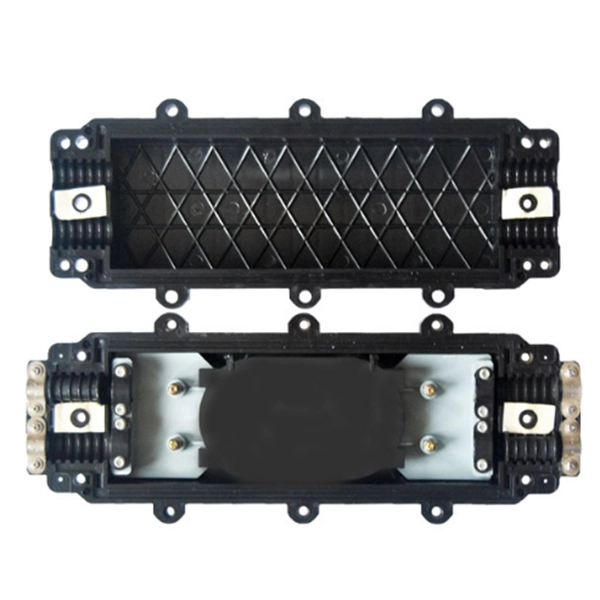
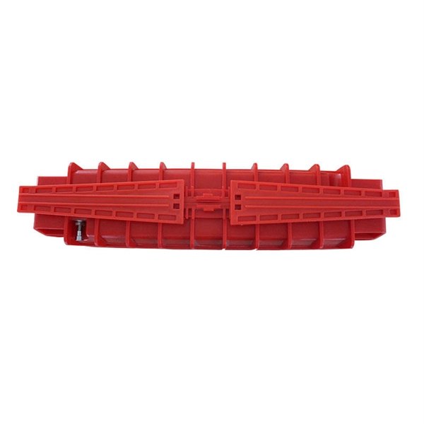
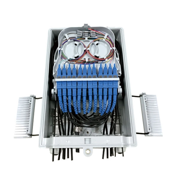
OPGW cable joint box installation involves several key stages: selecting the appropriate location, preparing both the cable and the joint box, splicing fibers, and sealing the joint box properly. Adhering to these steps ensures optimal performance and longevity of the telecommunications system. Optical fiber junction boxes are essential components in outdoor optical fiber cable installations. In this article, we will discuss the necessary steps and best practices. The Indoor/Outdoor Splice Box is a wall-mounted, indoor/outdoor fiber splice enclosure for centralized splice-only applications. These boxes are well suited as optical cable splice collection points for MDU (Multi-Dwelling Unit) residential fiber network applications, MTU (Multi-Tenant Unit). The installation of an optical cable junction box is crucial in ensuring the integrity and performance of optical networks. As we enter 2024, adhering to best practices not only enhances system reliability but also mitigates potential issues that can affect customer experiences. Installing a fiber optic splice closure efficiently and effectively requires attention to detail and. AFL's SB01 splice enclosure provides protection from all types of elements. From weather to bullets, the iron and steel construction requires no additional protective covering. Furnished with four plugged cable ports (2 aluminum and 2 plastic) for either All-Dielectric Self-Supporting (ADSS) or.
[PDF]
Lasers, modulators, and photodiodes form the core architecture of optical transceivers, enabling light-speed communication across global networks. Lasers generate the optical carrier. Modulators encode digital information. An optical transmitter is a crucial device used in fiber optic communication systems. Its primary function is to convert electrical signals into optical signals It involves modulating electronic system data and transforming it into light pulses using a laser or LED, and sending the pulses through. The optical transmitter and the optical receiver are the core components that enable this process, forming the electronic-to-optical and optical-to-electronic gateways necessary for modern, high-capacity data transmission. It takes data from an electronic system, uses a laser or LED to modulate that data into pulses of light, and then sends those pulses down the fiber. Together, lasers, modulators, and. At the core of a fiber optic system is the optical fiber – a flexible, transparent strand of glass, thinner than a human hair. Optical fiber is formed by drawing glass or plastic to a diameter slightly thicker than that of a. What are the main elements of an optical transmitter? Data decoder/demodulator, electrical interface, detector, optical interface.
[PDF]
Calibration & Repair services in Ireland. 5 day turn around with competitive pricing! View full electrical test and measurement equipment list here. is an independent calibration laboratory focused on meeting the total quality requirements of industry. Proper calibration of today's sophisticated test and measurement equipment is essential for preserving measurement accuracy, complying with international standards. Parameters covered include; Temperature, Humidity, Dewpoint, Various Gases, Pressure, Electrical, Weights & Scales, Analytical and some Specialist calibrations. Calibration is performed using the very latest Calibration Equipment/Standards & Calibration/Asset Management Software. Fast Efficient. PTM Calibration offers a wide range of services that complement our core business. We aim to be your one stop shop for all your calibration, test & measurement needs. From major blue chip companies & medium enterprises to small companies and sole traders. Including: aerospace, pharmaceuticals. OptiCal Sciences are an authorised service centre with service, repair and calibration experience and procedures for an extensive variety of models from a wide range of manufacturers.
[PDF]

Discover the key differences between optical fiber cables and copper cables. OPTRAL analyzes the advantages and disadvantages to enhance connectivity. Optical and copper interconnection technologies represent two distinct approaches to data transmission, each with its own advantages and limitations. While fiber optics dominate in performance, copper retains its technical and economic justification. But how do you decide which one is best suited for your needs? This article delves into the technical comparison between copper and fiber optic cables. When it comes to modern data transmission, Fiber Optic cables and Copper Cables play pivotal roles in ensuring seamless connectivity. What Are Fiber Optic Cables? Fiber Optic cables function by transmitting data in the form of light pulses through optically pure glass fibers. These fibers are. “Fiber offers multiple technical advantages, including exceptional bandwidth, low attenuation and distortion over long distances, reduced bulk, as well as isolation from electromagnetic interference (EMI) and electrostatic discharge (ESD). ” Let's explore the characteristics, advantages, and. The two core material technologies used in almost all cables are fiber optic, and copper wiring. Whether you're looking at an HDMI cable, a USB cable, Ethernet patch cable, or any other kind of network of data transmission cabling, they are all built using copper or fiber optic internal wiring.
[PDF]
The Italy optical fiber cable market is poised for significant transformation from 2026 through 2033, driven by a confluence of technological evolution, economic shifts, and evolving regulatory frameworks. is a leading company in the design and production of fiber optic cables, offering a comprehensive range for various applications. With a strong commitment to quality and innovation, Cavicel has established a global presence, ensuring their high-quality optical cables are recognized. Tratos is an international cable manufacturer with hundreds of thousands of square meters of facilities in Italy, the UK, Germany, and Spain. The company manufactures all the components of its cables, including conductors, insulating compounds, fiber optics, and finished cables. The production site. An innovative research center that brings together the entire Italian fiber optic communication network, where new technological solutions can be tested and developed, from fiber sensing to digital twin. As digital infrastructure investments accelerate across Europe, Italy's import-export.
[PDF]
All efforts have been made to incorporate all relevant up to date information available, any discrepancies or need for addition or deletion is felt necessarily may please be intimated to this office for further i.
[PDF]
The BERT800 series bit error tester employs a modular design, featuring a control board and interchangeable interface boards. This flexible architecture allows for testing a wide range of optical transceiver modules with different packages, including OSFP, QSFP-DD, and QSFP28. Bit Error Rate (BER) is an important factor in the performance of any data transfer channel, whether wired or wireless. It can be affected by a variety of factors, including signal to noise, distortion, and jitter, so accurate BER measurement helps to pinpoint problems. We offer a full range of. The global bit error rate tester (BERT) market is expanding significantly, driven by escalating demands for high-speed data transmission validation. Current estimates place the market at approximately $XX billion in 2024, with a projected CAGR of 8. The bit error rate (BER) represents the ratio of incorrectly received bits to the total number of transmitted bits over a. A bit error rate test (BERT) typically requires a test pattern generator and a receiver set to the same pattern. They can be used in pairs, with one at either end of a link, or singularly at one end with a loopback at the remote end. Versatile 10G multiservice test modules for lab and field. As transmission rates continue to accelerate, accurately measuring bit error rates in optical modules is crucial to ensure reliable performance.
[PDF]