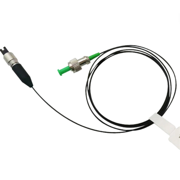
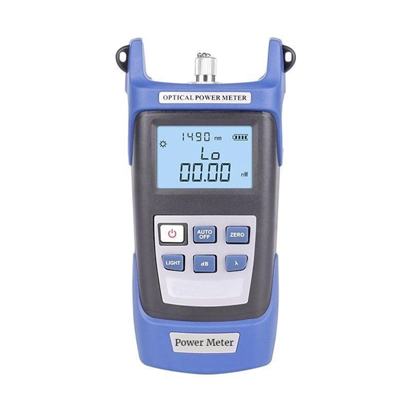
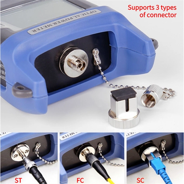
An optical power meter (OPM) works by converting light energy into electrical energy using a photodiode sensor. When light from a fiber optic cable hits the sensor, it generates a small electrical current related to the light's strength. Optical power meters are a key element in the optimization and maintenance of such optical networks and of their components. In this article, learn: What is an optical power meter? An optical power meter (OPM) measures the power levels of light signals in devices that transmit data or power using. An optical power meter (OPM) is a device used to measure the power in an optical signal. The term usually refers to a device for testing average power in fiber optic systems. It measures the optical power transmitted through a fiber, helping to verify if the light signal is strong enough for communication. Beginners may find it complex, but understanding its function makes it. This article provides a comprehensive overview of optical power meters, instruments used to measure the power of light beams. It details the main components, including sensor heads and display units, and explains the two primary sensor technologies: robust thermal sensors for high powers and. A fiber-optic power meter is a quantitative measurement instrument, not a diagnostic tool by itself.
[PDF]
In this video, we'll show you how to connect an energy meter to a distribution board (DB) safely and efficiently. energy meter connection with distribution box How to Connect an Energy Meter to Your Distribution Box Easily Steps to Properly Connect Your Energy Meter to a Distribution Box. Site/existing equip info - SFH (1 story, no basement, just crawlspace) w/ attached garage. 200A main service (Leviton panel). Covers wiring, placement, standards, and expert tips for a compliant setup. A distribution box is the heart of any electrical system. It takes the incoming power and safely distributes it to different circuits throughout your building. I am going to start digging a trench to run underground cable from a service pole breaker box to a well house; the distance is 60 feet. The breaker is a 240 V 2-pole 20-20 which will run to the well house water pump pressure switch. The present UF 2-10 AVG with ground cable runs two inches under. An electric meter box wiring diagram is a visual representation of the electrical connections and circuits involved in connecting an electric meter to the rest of the electrical system in a building. The diagram provides a clear and concise overview of how the meter is connected to the electrical. Limited the meter location from pad mount transformer for PSO. APCo and TX do not allow unistrut for installations. 7/2020 Revised Figure 15. Added wording for consistency with Section 8 of document.
[PDF]
This paper aims to study the design, simulation, and optimization of low-loss Y-branch passive optical splitters up to 64 output ports for telecommunication applications. For a waveguide channel profile, the standard material silica-on-silicon is used. Two important technologies for optical layer monitoring are Optical Performance Monitoring (OPM) and Optical Power Detection (OPD). Although they aim to maintain network health, they differ significantly in scope, technique, and deployment. This article delves into these differences, equipping. Optical Performance Monitoring (OPM) is considered a necessity over an optical network to enable sensibility of traffic line status and attain outstanding Quality-of-Service (QoS). The Y-splitters are designed and simulated at. Passive optical networks (PONs) are the network architecture of choice for residential fiber deployments. A PON is designed specifically to be cost-effective for delivering high data-rates to large customer populations. signals and various components of OPM functionalities are indispensable robust network operation and plays a key role flexibility and improve overall. Optical performance monitoring (OPM) is used for managing high capacity dense wavelength-division multiplexing (DWDM) optical transmission and switching systems in Next Generation Networks (NGN). OPM involves assessing the quality of data channel by measuring its optical characteristics without.
[PDF]
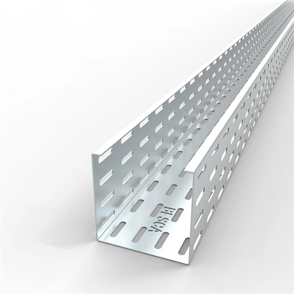
Need some clarification about NEC 770. 47 (B), it says that the direct buried conductive fiber optic cable shall be 12 in (300 mm) away from the power cables. Separating high-voltage power cables from low-voltage communication cables is a fundamental requirement in any electrical installation. This practice is mandatory for two distinct reasons: ensuring the safety of the structure and its occupants, and preserving the integrity of sensitive data. Maintaining proper separation between power, data, and limited energy cabling is foundational to system performance, safety, and code compliance. Separation isn't just an EMI precaution — it protects signaling, reduces rework, and ensures pathways meet inspection expectations across risers. TECHNICAL GUIDELINE July 30, 2020 TG030 Rev. 4 Pathway Separation Between Telecommunication Cables and Power Cables Communications cables are, by design or necessity, often installed in close proximity and/or in the same pathway as power service cables. The electrical energy of the power cables can. This standard titled “Commercial Building Standard for Telecommunications Pathways and Spaces” is a joint publication of ANSI/TIA/EIA. Its current version (ANSI/TIA/EIA/-569-B) was published in October 1, 2004 and describes EMI aspects in Article 10. ca with numerous contributions by others. "UTP Separation Guidelines From EMI Sources". The values are the same as the cabling pathways standard, EIA-569, table 4.
[PDF]

The actual number of optical modules used primarily depends on the following factors. Discrepancies in Calculating the Ratio of Optical Modules to GPU-The Varying Usage Quantity Due to Different Networking Architectures. Network Card Model. GPUs such as the A100, H100, and upcoming GH100 require high-speed optical interconnects to link thousands of GPU nodes, enabling large-scale AI model training and inference. Network Card Model It mainly includes two network cards, ConnectX-6. Traditional optical transceivers, especially in 400G and 800G deployments, generate significant heat and demand substantial power just to keep the lights blinking. 1) NIC Models Mainly includes two types of network cards, ConnectX-6 (200Gb / s, mainly used with the A100) mainly used optical modules are MMA1T00-HS (200G Infiniband HDR QSFP56 SR4 PAM4 850nm 100m) and ConnectX-7. Two complementary approaches are used to grow these systems: scale-up (tightly coupling many accelerators as one unit) and scale-out (networking multiple units across racks or clusters). In both cases, optical connectivity is playing an increasingly vital role. Below, we explain the trends in. While the industry-standard OSFP (Octal Small Form-Factor Pluggable) module has successfully enabled 400Gbps, 800Gbps, and 1. 6Tbps optical pluggable modules , it is limited to 32 modules per Rack Unit (RU), typically requiring 2 RUs to achieve 102. 4Tbps and 4 RUs to reach 204. 8Tbps of switching.
[PDF]
To meet the needs of multi-way power distribution applied to high-power solid-state sources, a multi-way power distribution device based on coaxial waveguide is designed and studied. In this work, two dynamically tunable power dividers using waveguide ENZ media are proposed by precisely modulating the internal magnetic field and the widths of the output waveguides. The first approach features a mechanically reconfigurable ring-shaped ENZ waveguide. By analyzing the transmission characteristics of coaxial waveguides and by applying the theory of impedance. In this paper, an E -plane stepped-impedance transformer and Y-junction bifurcation are used to form a waveguide power divider with ceramic substrate loaded with thin film resistors. This structure is realized high isolation in V-band by inserting a ceramic substrate at the H -plane center of the. A numerical model of an equal power divider based on the 4-branch single-mode waveguide is proposed. This proposed design does not require extra fabrication process and supplementary structure modification compared to other typical multibranch waveguides. The condition of uniform output power.
[PDF]
The most common causes of a fluctuating multimeter reading is due to a bad connection or loose wiring in the circuit. In order to investigate this possibility you will need to thoroughly inspect all of your connections and wires for any signs of oxidation, corrosion, fraying or. However, what happens when your multimeter starts behaving erratically, displaying fluctuating readings instead of stable values? This seemingly minor issue can lead to misdiagnosis, wasted time, and even potential safety hazards. Understanding the reasons behind a jumping multimeter reading is. The reading displayed on the meter is affected by factors like voltage drop across components in the circuit being tested. If this reading keeps jumping around unexpectedly it could indicate a problem in the circuit itself. Measuring Current: For current measurement, I switch the multimeter to the current setting. This method allows me to see how much current flows through. This guide delves into the various causes of multimeter fluctuations and provides practical solutions to ensure accurate. From fluctuating readings to unresponsive display screens, recognizing these common issues early on can prevent costly mistakes and potential hazards. These types of issues can often be fixed by replacing faulty wiring and securing.
[PDF]
The most common and effective solution is the preformed tension clamp. This fitting consists of a set of helical rods that are wrapped around the cable, a thimble (clevis), and an extension link. The helical rods are designed to transfer the tensile load from the cable to the anchor. The function of the remaining cable rack is to store reserved optical cables, which are generally used on tensile towers (poles). There are two types: Inner button and outer disc. When the remaining cable rack is used for installation on the iron tower, it is equipped with two small splints. Additionally, adapters are available for the steel towers and steel and concrete poles. maintain alignment of and. ficing corrosion resistance. It is best suited to applications with moderate to low span ut increasing fibre strain. 3mm2 RRU Power cable. Without additional adapters, these clamps can provide sturdy, reliable, long-term support to systems. We manufacture a wide range of hardware fittings for OPGW Optical Ground Wire, including Suspension and Tension Assemblies, Down Lead clamps, Earthing Clamps, Splice Enclosure, Reinforcing Rods, Vibration Dampers, etc. Find many great new & used options and get the best deals for 5x Huawei Optical Cable Fixing Clamp 2x3 C Type Bracket Cable Clamp 27150086 at the best online prices at eBay! Free shipping for many products!.
[PDF]
It performs error detection and alarm monitoring, serving as an essential tool for bit error testing in R&D and production of optical modules/ devices. Bit Error Ratio Tester is an instrument used to test and analyze bit error ratio in digital transmission systems, fiber optic communication systems, and digital microwave communication systems. Dimension Technology's BERT800 bit error tester series offers a comprehensive solution for testing and verifying high-speed optical transceiver modules. OPTELLENT is a provider of broadband test and measurement solutions for communications. The Company's test & measurement solutions are used in product development, manufacturing. As transmission rates continue to accelerate, accurately measuring bit error rates in optical modules is crucial to ensure reliable performance. There are three interchangeable slot boards which include QSFP, SFP+ and SFP ports separately. QSFP, SFP+ and SFP ports follow QSFP MSA, SFP+ MSA and SFP MSA. The user interface allows you to individually monitor bit error rate, error count and timer by connecting to PC via USB cable. In high-speed digital communication systems, even the smallest bit-level error can compromise performance, reduce efficiency, or lead to costly rework.
[PDF]
Calibration & Repair services in Ireland. 5 day turn around with competitive pricing! View full electrical test and measurement equipment list here. is an independent calibration laboratory focused on meeting the total quality requirements of industry. Proper calibration of today's sophisticated test and measurement equipment is essential for preserving measurement accuracy, complying with international standards. Parameters covered include; Temperature, Humidity, Dewpoint, Various Gases, Pressure, Electrical, Weights & Scales, Analytical and some Specialist calibrations. Calibration is performed using the very latest Calibration Equipment/Standards & Calibration/Asset Management Software. Fast Efficient. PTM Calibration offers a wide range of services that complement our core business. We aim to be your one stop shop for all your calibration, test & measurement needs. From major blue chip companies & medium enterprises to small companies and sole traders. Including: aerospace, pharmaceuticals. OptiCal Sciences are an authorised service centre with service, repair and calibration experience and procedures for an extensive variety of models from a wide range of manufacturers.
[PDF]
FBT splitters are more sensitive to fiber bending and environmental expansion, particularly under uneven thermal conditions. A beam splitter or beamsplitter is an optical device that splits a beam of light into a transmitted and a reflected beam. It is a crucial part of many optical experimental and measurement systems, such as interferometers, also finding widespread application in fibre optic telecommunications. a laser beam) into two (or sometimes more) beams, which may or may not have the same optical power (radiant flux). Different types of beam splitters exist, as described in the. Fiber optic splitters distribute optical power from one input fiber to multiple output fibers through either fused biconical taper (FBT) coupling or planar lightwave circuit (PLC) waveguide structures. Their performance depends on optical symmetry, waveguide integrity, and mechanical stability of. : The invention provides a light generating system (1000) comprising a first light generating device (110), a second light generating device (120), a luminescent material (200), a diffuser assembly (700), optical elements (500) comprising a first redirection optical element (1510), and a light exit. When splitting one incident light beam into two separate beams, beamsplitters are applied. Depending on the beam split based on intensity, wavelength, or polarization, its level of optical power on beam penetration differ. Just to mention few, these beamsplitter components are commonly required for.
[PDF]
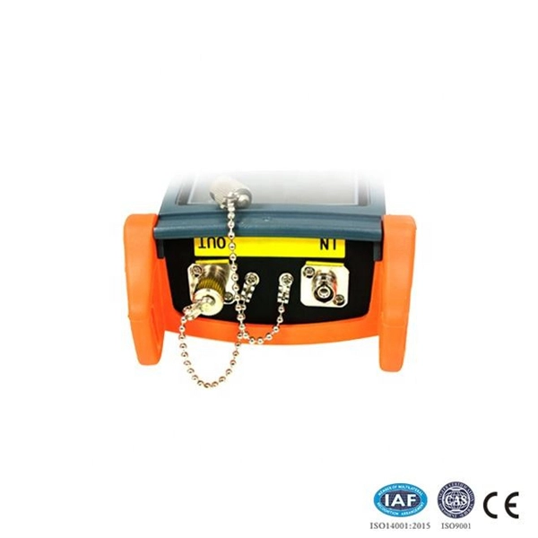
Full Technical Specifications: Explore our complete range of directional and dual directional couplers, featuring ultra-wideband operation from 0. This catalog details models with coupling values from 5 dB to 50 dB and power ratings up to 500 Watts. How does 6W market outlook report help businesses in making decisions? 6W monitors the market across 60+ countries Globally, publishing an annual market outlook report that analyses trends, key drivers, Size, Volume, Revenue, opportunities, and market segments. This report offers comprehensive. IPP's directional couplers offer some of the widest bandwidths at the highest power levels in the industry. These directional couplers are available in frequencies from 1 MHz., in power. Directional couplers are critical components in radio frequency (RF) and microwave systems, used to split or combine signals while maintaining signal integrity. These passive devices allow a signal to be directed from one port to another, with a portion of the signal being coupled to an auxiliary. We are an RF / Microwave / Wireless Telecom Manufacturer for component, modules and systems. We offer the widest range and best performance RF Directional Couplers and Quadrature Hybrids in the world, extremely aggressive pricing structure. RF directional couplers often. CorechTEK's Directional Couplers are engineered for precise RF and Microwave signal monitoring and power sampling. CorechTEK Couplers.
[PDF]
Use this selector tool to quickly identify the best power supply for your aerospace and defense ATE requirements. Explore engineer-authored content and a vast knowledge base with thousands of learning opportunities. Use 25+ X-Series applications to analyze, demodulate, and troubleshoot signals across wireless, aerospace/defense, EMI, and phase noise. With extra memory and storage, these enhanced NPBs run Keysight's AI security and performance monitoring software and AI stack. Achieve fast, accurate board-level. Fiber-optic switches control light paths within fiber optics, ranging from simple on/off types to complex matrix configurations like 64×64. Fiber-optic switches are optical switches in the context of fiber optics. They're a core component in fiber-optic networks, where data travels as pulses of light through glass fibers. This technology allows for high bit rate transmission to be switched between various optical lines. All of these optical switches are purely optical path, there is no optical to electrical to optical conversion. Click to jump to class of switch --- Provides a bypass of.
[PDF]
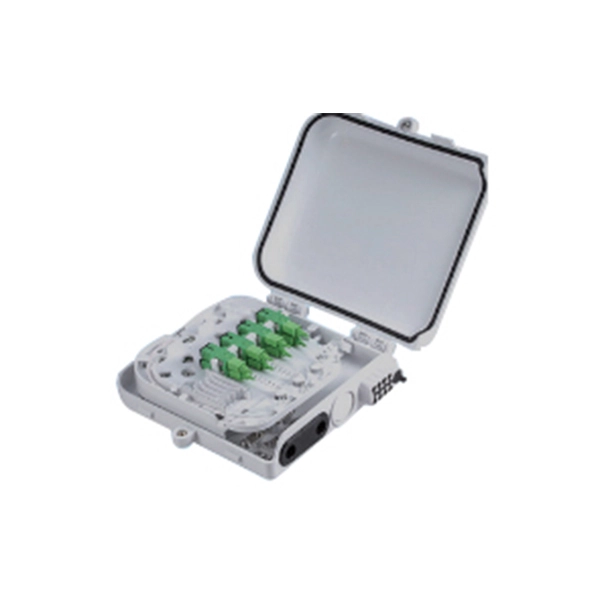
With a powerful 40KM transmission capability and SC interface, this GPON OLT module is fully compatible with Huawei, ZTE, and Cisco devices. Built for carrier-grade reliability, it ensures stable, high-speed data transmission in fiber-to-the-home (FTTH) and enterprise GPON. The SFP-FE-SX-MM1310 (part number: 02315233) is a Huawei-certified 100M optical module. However, the Vendor Name field displays the original manufacturer name, instead of HUAWEI. Huawei. For Class C+ module, it can support with 64 ONUs at most. OptiXstar MA5671A is a mini plug-and-play Passive Optical Network (PON) access device an Optical Network Unit (ONU) that supports one-stop deployment, even achievable offline when using Gigabit-capable Passive Optical Network (GPON) upstream transmission. Once deployed, OptiXstar MA5671A. Huawei SFP GPON OLT C+ is fit with Huawei OLT devices like MA5608T MA5683T and MA5680T. It is inserted in devices such as routers or network interface cards which provide one or more transceiver module slot. Huawei. Haile GPON OLT Optical Fiber Module SFP-GPON-OLT-40 is a high-performance optical transceiver designed for long-distance fiber optic communication.
[PDF]
A WDM system uses a multiplexer at the transmitter to join the several signals together and a demultiplexer at the receiver to split them apart. With the right type of fiber, it is possible to have a device that does both simultaneously and can function as an optical add-drop. In fiber-optic communications, wavelength-division multiplexing (WDM) is a technology which multiplexes a number of optical carrier signals onto a single optical fiber by using different wavelengths (i., colors) of laser light. This technique enables bidirectional communications over a. WDM is a fiber optic transmission technique that leverages multiple light wavelengths to transmit data efficiently over a single medium. WDM technology employs different optical wavelengths, or colors, of laser light to multiplex several optical carrier signals onto a solitary optical fiber. Each. There are a lot of people who don't understand the difference between WDM and optical splitter. This allows multiple channels of data to be transmitted simultaneously. WDM technologies allow organizations to place equipment at either end of a fiber pair and combine multiple wavelength channels on a single fiber pair instead of using multiple separate fibers pairs for every separate service. The article explains the fundamental principle and its.
[PDF]