The BDCOM S5828 employs a cutting-edge hardware architectural design to deliver the best switching performance and a wealth of data center service capabilities available in the market. Bangladesh - Shop for Best Online at Daraz. bd Wide Variety of sfp network switch. Great Prices, Even Better Service. Modular All Brands BDCOM BDCOM RX1550 1. Image may differ with actual product's layout, color, size & dimension. No claim will be accepted for image mismatch. Product data used in this website is based solely on its manufacturer provided information, authenticity and. This Small Form-Factor Pluggable (SFP) module is a compact, pluggable transceiver module that is used in your networking and telecommunication system. It is mainly used for fast data transfer over Ethernet, fiber optic or copper cables, and is also suitable for installation in switches, routers. The BDCOM S5800 series switch is a new generation of high-performance data center all-Gigabit TOR switch launched by Shanghai BDCOM Co. for high-performance cloud computing, data centers, and high-end campus networks.
[PDF]
The mlxlink tool is used to check and debug link status and issues related to them. In order for mlxlink to function properly, make sure to update the firmware version to the latest. In this context, PHY can be understood as an optical module. When testing PRBS, there are 3 test nodes: MAC ----> PHY, PHY -----> MAC, and PHY ----- PHY. Signal testing can be performed through these 3 different nodes. and detection in MAC testing. Example: For device N9200-64DC, test ports. Qualcomm chips are now the core of high-speed optical modules for 5G networks, data centers, and enterprise interconnects. These modules leverage advanced signal processing, modulation, and high-speed interfaces to provide high bandwidth, low latency, and reliable performance. During use, reading optical module information helps understand its real-time operating status, enabling faster troubleshooting of link abnormalities. The following uses the. This article provides instructions on how to view the Optical Module Status on your switch through the Command Line Interface (CLI). The Cisco Small Business Series Switches allow you to plug in a Small Form-factor Pluggable (SFP) transceiver in their optical modules to connect fiber optic cables. mlxlink is. Could you please provide me some steps on how to enable ICMP debug on the 3850 to find the root cause of the problem? Thanks! Hello Eyad There are a couple of things that come to mind that may help you in your troubleshooting.
[PDF]
The system in this example contains the following elements: 1. 2 Pseudo-random Bit Stream (PRBS) block 2. 2 NRZ Pulse Generator (NRZ) 3. 1 CW Laser (CWL) 4. 3 1x2 Fork (FORK) 5. 2 Electrical Not Gate (N.
[PDF]
The operating principle of an OCS is similar to telephone circuit switching. When two ports need to communicate, the controller configures a path in the optical switch matrix, using optical components to route the optical signal from one fiber to another, forming an independent. Optical switching represents a fundamental technological evolution, shifting data routing from the domain of electrons to the realm of photons, or light. This transition allows data to remain in its native optical form as it travels through fiber optic networks, eliminating the need for. Optical switches are devices that route light signals from one path to another without converting them into electrical signals first. They're a core component in fiber-optic networks, where data travels as pulses of light through glass fibers. Every time that light needs to change direction or jump. Optical switches, a key component in modern network infrastructure, are devices used in optical fiber networks for signal management. Unlike traditional electrical switches, which transmit data as electrical signals, optical switches handle data transmission in the form of light. These devices play a critical role in modern optical networks by enabling dynamic reconfiguration, wavelength routing, and protection switching. In this article, we will explore the fundamentals of optical switches, their types, and their applications in various fields. An optical switch is a.
[PDF]
Use this selector tool to quickly identify the best power supply for your aerospace and defense ATE requirements. Explore engineer-authored content and a vast knowledge base with thousands of learning opportunities. Use 25+ X-Series applications to analyze, demodulate, and troubleshoot signals across wireless, aerospace/defense, EMI, and phase noise. With extra memory and storage, these enhanced NPBs run Keysight's AI security and performance monitoring software and AI stack. Achieve fast, accurate board-level. Fiber-optic switches control light paths within fiber optics, ranging from simple on/off types to complex matrix configurations like 64×64. Fiber-optic switches are optical switches in the context of fiber optics. They're a core component in fiber-optic networks, where data travels as pulses of light through glass fibers. This technology allows for high bit rate transmission to be switched between various optical lines. All of these optical switches are purely optical path, there is no optical to electrical to optical conversion. Click to jump to class of switch --- Provides a bypass of.
[PDF]
To connect copper wire cables to optical fiber cables, you need a media converter that supports 1000BASE-T. To connect an optical fiber cable to a switch, we recommend that you install a module such as a SFP (mini-GBIC) or GBIC in the switch instead of using a stand-alone media converter. Also, we. Fiber optic audio cables, also known as optical audio cables, have revolutionized the way we transmit audio signals. This cutting-edge technology offers superior sound quality, higher bandwidth capacity, and immunity to interference, making it a popular choice among audiophiles and professionals in. There are two types of SPDIF connections: coaxial and optical. Coaxial SPDIF uses an RCA connector, similar to a composite video connection, to transmit audio signals. What Is Optical? Optical. In this comprehensive guide, we'll delve into the intricacies of optical audio, walk you through the process of connecting your devices, and provide valuable insights on setting up your AV receiver for optimal performance. These light pulses travel through the cable without interference or signal. CAPS Pipeline with HDPlex Linear PSU running Win10 64 bit, AO 2. 0, RoonServer, HQPlayer -> T+A DAC8 DSD -> Linear Tube Audio's MicroZOTL2 Headphone Amp with Mojo Audio's Illuminati Linear PSU -> Focal Utopia/Audeze LCD-3 I 100% agree with your statement, however, I'm afraid the horde of.
[PDF]

The short answer is no - RJ45 connectors are designed for electrical Ethernet signals, while fiber optics transmit light pulses through glass or plastic. However, modern networks often combine both technologies. A combo port, also known as an optoelectronic multiplexing interface, is a photoelectric composite port with two kinds of Ethernet interfaces (RJ45 port and SFP port) on an Ethernet switch. In other words, it is a compound port that can support two different physical layers and share the same. Optical ports on switches typically require the insertion of optical modules for data transmission over fiber optics. However, these two different physical ports can not be used at the same time. If you wake up the RJ45 port, the corresponding SFP port will. Ensuring seamless interoperability and compatibility between optical transceiver modules and network devices is crucial for maximizing network performance, reducing downtime, and controlling operational costs. This guide dives deep into the core aspects of optical transceiver compatibility, common. SFP (Small Form-factor Pluggable) is a compact, hot-pluggable network interface module used to connect network devices (switches, routers, firewalls) to fiber optic or copper cables. Think of it as the “translator” for your network equipment, converting electrical signals into optical signals.
[PDF]
Yes, fiber cables can be bent during installation, which proves particularly useful when you pull cables into position rather than using blown installation methods. Blown fiber installation uses air pressure to propel cables through conduits, minimizing bending stresses. Fiber optic cables are designed to withstand some bending, but excessive bends can physically damage the glass fiber or cause significant signal loss. That's why every fiber cable has a minimum bend radius specification provided by the manufacturer. The minimum bend radius defines the smallest. All fiber optic cables have specifications that must not be exceeded during installation to prevent irreparable damage to the cable. Installers must understand these specifications and know how to install cables without. The bend radius of fiber cables is critical for maintaining high performance and longevity. A practical single-mode fiber option for compact routing, dense fiber management, FTTH access, and reel-based systems such as drone fiber and FPV fiber tether where bend-loss control matters in real installation and maintenance conditions. The tighter the bend, the smaller the radius. The minimum bend. Astel 4 Core Siamese model has 2 x 2 Fiber cables joined in the center by steel messenger. Its main advanctage is that a single cable can be used for 2 independent telecom operators. The optical fiber is made of high pure silica and.
[PDF]
OFC 2020 returns to San Diego Convention Center, San Diego, California, 8-12 March 2020 for another groundbreaking program as the world's largest conference and exhibition for optical communications and networking. SAN DIEGO — Explore the latest in optical communications innovation, data-center connectivity, machine learning/artificial intelligence (AI), applications of optical networks in 5G and cloud computing at The Optical Networking and Communication Conference & Exhibition (OFC), the single-most. This program contains the latest information up to 21 January 2020. Considered the hub of the industry, OFC represents the entire ecosystem—from. OFC 2020 - Optical Networking and Communication Conference & Exhibition, co-sponsored by OSA (Optical Society of America) and the IEEE Photonics Society. The OFC audience spans the entire industry, from scientists and engineers to manufacturers and service providers. It provides the industry's most. *** This is a print representation of what appears in the IEEE Digital Library. Some format issues inherent in the e-media version may also appear in this print version. Chen. The printed show guide for the exhibition contains a list of 181 booth cancellations, which the event organizers indicate was accurate as of March 2. A corner of the OFC 2020 show floor at 2:15 PM PDT on March 10. The exhibit floor at OFC 2020 in San Diego opened today. Reports from sources in.
[PDF]

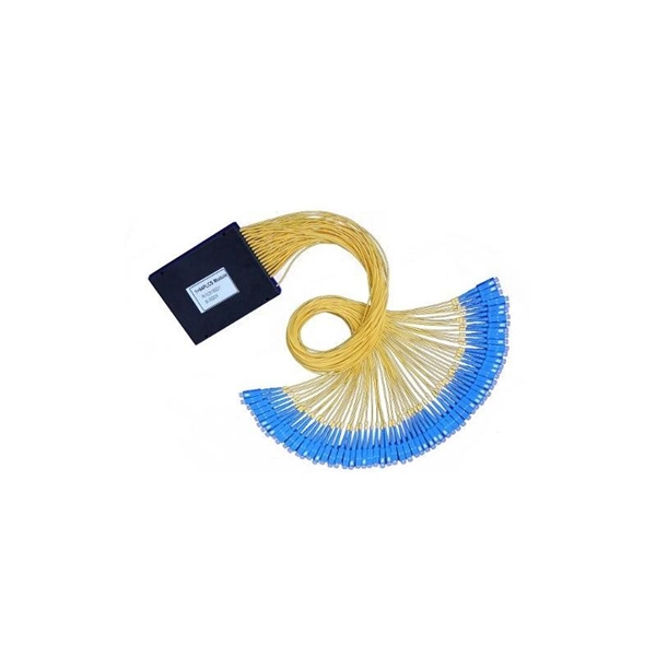
At its core, a fiber optic splitter relies on the principles of light reflection, refraction, and waveguiding to divide signals. Its design varies by type, but the underlying mechanism involves manipulating light to distribute its power across multiple output ports. A fiber optic splitter is a passive optical component that divides a single incoming optical signal into two or more outgoing signals, or combines multiple incoming signals into one. Their ability to efficiently manage optical signals makes them indispensable in various. This guide will demystify this pivotal passive device, exploring its types, working principles, and how it seamlessly integrates with optical transceivers to bring high-speed internet to your doorstep. 📄 What is an Optical Splitter? An Optical Splitter, also known as a beam splitter, is a passive. Fiber optic splitter is a passive optical device that includes multiple input and output ends. This principle allows a single input light beam to be split into N output light beams. The splitting can be achieved through two main methods: parallel beam splitting and beam divergence splitting. For example, an optical splitter.
[PDF]
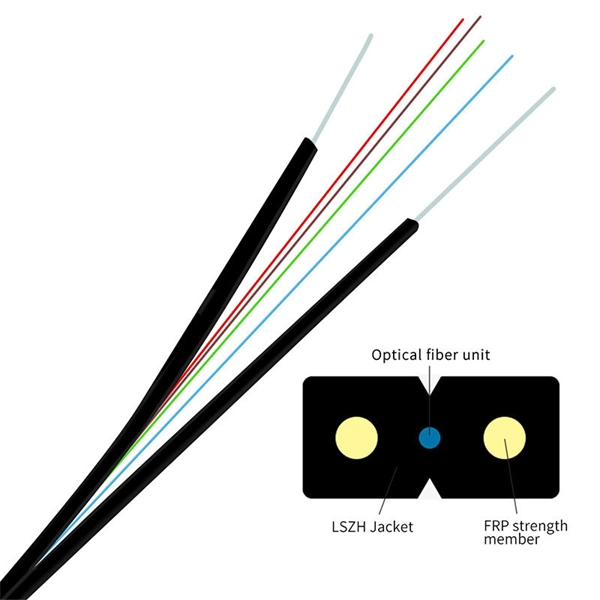
Optical fiber consists of a and a layer, selected for due to the difference in the between the two. In practical fibers, the cladding is usually coated with a layer of or. This coating protects the fiber from damage but does not contribute to its properties. Individual coated fibers (or fibers formed into ribbons or bundles) then ha.
[PDF]
This document discusses techniques for trenching and laying optical fiber ducts. Installing fiber optic cables underground involves far more than digging trenches and placing cables. It forms a critical backbone for modern communication networks across both urban and rural environments. Project success depends on careful planning, precise installation practices, and proper. Installing underground fiber optic cables is critical to establishing high speed internet infrastructure that delivers reliable connectivity for businesses nationwide. Fiber optic cables are the shining stars of modern connectivity, transmitting data at lightning-fast speeds through glass. This comprehensive guide walks through the essential steps and best practices for successful underground fiber optic cable deployment, ensuring optimal performance and longevity of your network installation. Why Choose Underground Fiber Optic Installation? Underground fiber optic installations. Placing cables underground has the added benefits of reducing transmission losses, aiding planning consent and reduced risk of service supply loss through extreme weather.
[PDF]
This report provides a comprehensive assessment of recent tariff adjustments and international strategic countermeasures on Optical Modules cross-border industrial footprints, capital allocation patterns, regional economic interdependencies, and supply chain reconfigurations. Global Optical Modules Market Size By Product Type (Transceivers, Transponders), By Technology Type (Single-Mode Fiber (SMF), Multi-Mode Fiber (MMF)), By Application (Telecommunications, Data Centers), By Data Rate (10 Gbps, 25 Gbps), By Form Factor (SFP (Small Form-Factor Pluggable), SFP+. The global market for Optical Modules was estimated to be worth US$ 17590 million in 2024 and is forecast to a readjusted size of US$ 56786 million by 2031 with a CAGR of 15. 8% during the forecast period 2025-2031. The potential shifts in the 2025 U. 7% during the forecast period MARKET INSIGHTS The global Optical Module Package Market was valued at 8942 million in 2024 and is projected to reach US$ 20220 million. Get a sneak peek into the valuable insights and in-depth analysis featured in our comprehensive optical module integration market report. Download now to stay ahead in the industry! Need more tailored information? Ketan is here to help you find exactly what you need. Get a sneak peek into the.
[PDF]
Need some clarification about NEC 770. 47 (B), it says that the direct buried conductive fiber optic cable shall be 12 in (300 mm) away from the power cables. Separating high-voltage power cables from low-voltage communication cables is a fundamental requirement in any electrical installation. This practice is mandatory for two distinct reasons: ensuring the safety of the structure and its occupants, and preserving the integrity of sensitive data. Maintaining proper separation between power, data, and limited energy cabling is foundational to system performance, safety, and code compliance. Separation isn't just an EMI precaution — it protects signaling, reduces rework, and ensures pathways meet inspection expectations across risers. TECHNICAL GUIDELINE July 30, 2020 TG030 Rev. 4 Pathway Separation Between Telecommunication Cables and Power Cables Communications cables are, by design or necessity, often installed in close proximity and/or in the same pathway as power service cables. The electrical energy of the power cables can. This standard titled “Commercial Building Standard for Telecommunications Pathways and Spaces” is a joint publication of ANSI/TIA/EIA. Its current version (ANSI/TIA/EIA/-569-B) was published in October 1, 2004 and describes EMI aspects in Article 10. ca with numerous contributions by others. "UTP Separation Guidelines From EMI Sources". The values are the same as the cabling pathways standard, EIA-569, table 4.
[PDF]
Below is a detailed comparison table of typical optical module speeds ranging from 1G to 400G, highlighting wavelength, reach, power budget, connector type, data rate, and operating temperature. Optical modules, also known as transceivers, convert electrical signals to optical signals and vice versa. They come in multiple speed grades standardized by IEEE 802. 3, enabling data rates from 1 Gbps (Gigabit Ethernet) up to 400 Gbps (400G Ethernet). The choice of module speed directly impacts. We provide an industrial-grade reference framework, complying with the latest MSA (Multi-Source Agreement) updates, including SFF-8679 Rev 1. 4 (Jan 2025), to help you design robust, scalable optical fabrics. The Master Reference Matrix: SFP vs. QSFP Standards (2025 Edition) This table. Upgrade to 100G or 400G optics and save. Cisco Transceiver Modules - Learn product details such as features and benefits, as well as hardware and software specifications. How does our search work? With MEET OPTICS search you get direct access to our database of thousands of optical components from providers worldwide. com, we specialize in Cisco-compatible and NS Comm transceivers, offering enterprise customers tested, certified. SFP (Small Form-factor Pluggable) is a compact, hot-pluggable network interface module used to connect network devices (switches, routers, firewalls) to fiber optic or copper cables.
[PDF]