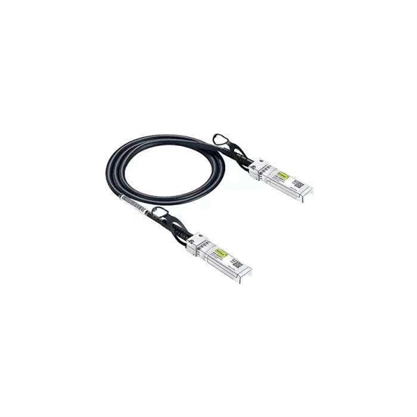
Learn how to choose the right fiber patch cord supplier by comparing price vs. quality, certifications, and delivery reliability. Back to Products & Services All Cable Assemblies Cable Assemblies Active Electrical Cable Solutions Active Optical Cables (AOC) AirBorn FOCuS Rugged Active Optical Cables Custom Cable Assembly Solutions Direct Attach Cable (DAC) Assemblies Fiber Optic Cable Assemblies HSAutoLink Interconnect System. Check each product page for other buying options. Need help?. Nano-Giga offers a wide range of fiber optic connectors and patch cords to suit your applications. The quick and professional support we receive from PTspeed ensures we always have what we need, when we need it. They're not just any supplier; they're an online supplier with robust in-stock. The fiber optic cable is used to connect or patch one optical device to another. Each end of the fiber optic cable has a connector that allows the installer to quickly connect or disconnect the cable as needed. They are very convenient. You will find the cable is. This guide will help you understand how to evaluate suppliers and make an informed decision when sourcing fiber optic patch cords for your projects — from FTTH deployments and Data Centers to Industrial Networks and Telecommunications Infrastructures. Tip: Many high-quality fiber patch cord.
[PDF]
Positive busbars, which collect all positive connections. Key Steps: When wiring a pair of 12V busbars, connect the positive terminal of each load to a stud on the positive busbar and their negative terminal to a stud on the negative busbar. 5' above batteries on inside of cockpit combing below decks. Install one new positive bus bar beside the negative one separated by about two inches 3. Positive and negative busbars are physically identical apart from the red/black colours used by some manufacturers to visually differentiate between. A Complete Guide to Battery Terminal Connector Types The store will not work correctly in the case when cookies are disabled. JavaScript seems to be disabled in your browser. For the best experience on our site, be sure to turn on Javascript in your browser. Skip to Content Blog Sign In Create an. This image illustrates a standard car battery with top post terminals and labeled connectors for the positive (+) and negative (–) ends, emphasizing safe and correct installation. A battery terminal connector is a fitting or clamp that attaches to a battery's terminal to connect a cable. In other. Both positive and negative terminals are the soul of the electrical system of the car, allowing the engine to start while keeping other components running. The catch? Mix-up or loose connection can cause electrical failure, drained batteries, and damage to wiring. This blog guides you how the two.
[PDF]
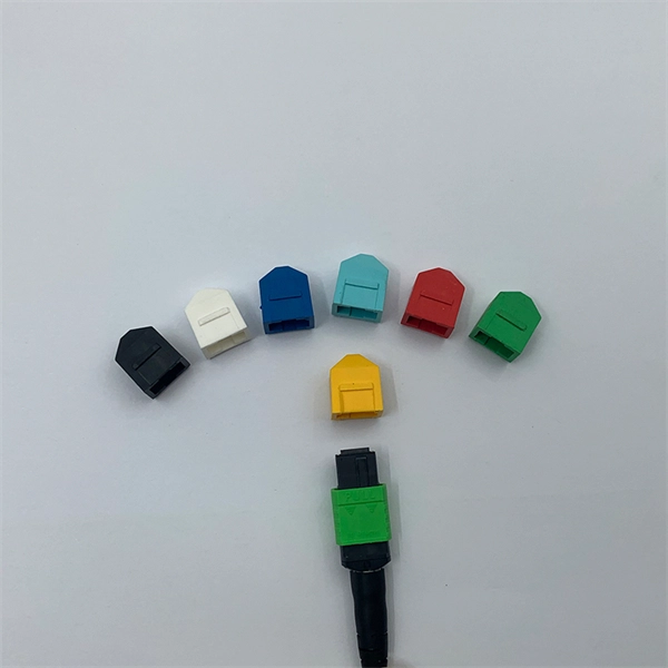
The simplest method: connect two cables pre-connectorized via a coupler (also called an adapter). The coupler aligns the two ferrules of the connectors using a zirconia sleeve. Why connect two fibers? Do you need to extend, repair, or connect two fiber optic cables? There are three methods main ones, each with its advantages and limitations. This article explains when. Optical fiber fast connectors, also known as cold connectors, are becoming increasingly popular due to their ease of use and quick installation. Unlike traditional fiber connectors that require epoxy and polishing, fast connectors use a mechanical splice to join the fibers. Another method is using a mechanical splice which involves aligning and securing the fiber ends with a precision. Fiber optic cables can be connected together using a couple of different methods: 1. This creates a permanent and low-loss connection. Connectors play a crucial role in our daily lives, yet there are some connectors that remain less familiar, such as fiber optic fast connectors. The goal is clean.
[PDF]
There are currently three methods of looking inside a fiber optic connector: (1) Non-destructive X-ray (2) Lossless sonar (3) Destructive cross section These methods help engineers determine the causes and effects of fiber optic connector failures and monitor the connector assembly. There are currently three methods of looking inside a fiber optic connector: (1) Non-destructive X-ray (2) Lossless sonar (3) Destructive cross section These methods help engineers determine the causes and effects of fiber optic connector failures and monitor the connector assembly. Fiber Optic Center offers a unique cross-sectioning service to identify and isolate problems related to fiber optic terminations that would otherwise be invisible. All. There are two major uses for visual inspection of fiber optic connectors. Video microscopes should have ability to record images and some may have ability to analyze connector condition to standards. Look for dirt, contamination, scratches or any other problem. Since connectors are susceptible to damage that is not immediately obvious to the naked eye—the inspection phase is vital. When proceeding with the inspection of connectors, there are two main components to inspect: the connector itself and the ferrule. With the press of a single button, FOCIS Flex auto-focuses, captures and centers the end-face image, applies Pass/Fail rules, displays image and Pass/Fail results, saves results internally and/or wirelessly transfers data to a.
[PDF]

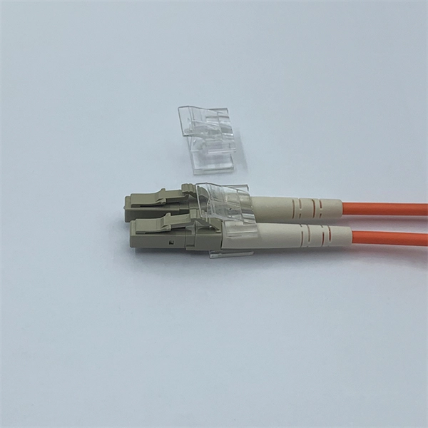
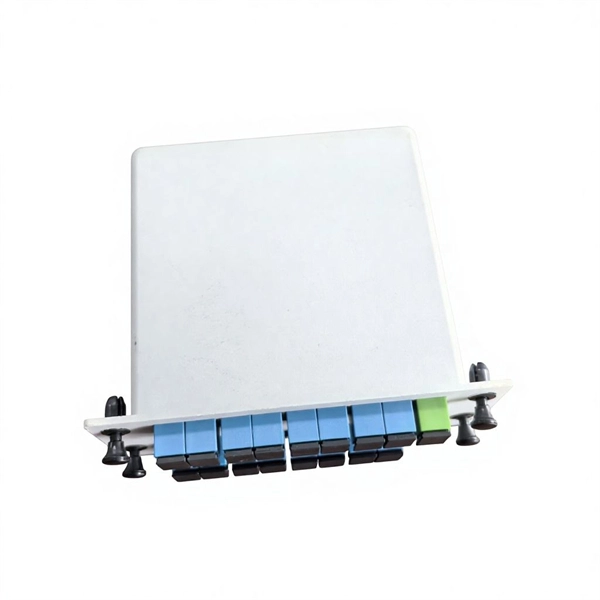
In this guide, we'll walk you through the entire process of preparing fiber optic cable for splicing and termination to fiber connectors. We'll explore the necessary tools, safety precautions, and step-by-step procedures for cable connectors, mechanical and. This article will guide you through the necessary tools, materials, and methods on how to connect fiber optic cables effectively, ensuring you achieve optimal performance from your fiber optic network. Have a network installation project? Fiber Optic Cables: The primary medium for your connections. There are many types of fiber optic connectors, including SC, LC, FC, ST, D4, MU, MT/MPO, etc. These connectors can be divided into single-mode and multi-mode fiber optic connectors according to their structure and purpose. Fiber optic connectors play an essential role in the realm of optical communication, enabling seamless connections between fiber optic cables. At the heart of any robust fiber optic network lies a crucial process: Preparing a fiber cable for termination of a connector or splice. Whether you're installing a new network, expanding an existing one, or. Fiber optic internet delivers blazing-fast speeds and reliable connectivity, making it a top choice for modern homes and businesses.
[PDF]
EIA/TIA 568 B allows any fiber optic connector as long as it has a FOCIS (Fiber Optic Connector Intermateability Standard) document behind it. Fiber optic cold connection, also known as mechanical splicing, is a widely used method of connecting optical fibers in a network. Unlike fusion splicing, which uses heat to join two optical fibers together, cold connection uses mechanical means to create a stable and low-loss connection. Unlike fiber splicing, which is permanent, connectors allow for easy connection and disconnection of cables, making them ideal for maintenance and flexibility in. Fiber optic joints or terminations are made two ways: 1) splices which create a permanent joint between the two fibers or 2) connectors that mate two fibers to create a temporary joint and/or connect the fiber to a piece of network gear. These terminations must be of the right style, installed in a. Fiber termination refers to the process of preparing the end of a fiber optic cable to connect to another fiber, a device, or a network. Proper termination is essential for ensuring optimal performance, reducing signal loss, and maintaining the durability of the connection. Since the introduction of fiber optic technology decades ago, a variety of connector types have been.
[PDF]
NADDOD Cisco compatible OSFP-800G-2xFR4 Optical Transceiver Module is a high-speed, low-latency solution designed for 800GBASE-2xFR4 Ethernet with link lengths up to 2km over single-mode fiber (SMF) using dual duplex LC connectors. This transceiver is compliant with IEEE 802. 3cu, OSFP MSA standards. Class1/1M Standard Product, Compliant with RoHS Environmental Protection Standards (Lead-Free). DDM (Digital Diagnostic Monitoring) Supported. 30-Day Free Return, 1-Year Free Replacement, 3-Year Warranty, Lifetime After-sales Technical. The QSFPTEK QT-OSFP-400GSi-DR4 is a transceiver module designed for 500m optical communication applications, and it is compliant with OSFP MSA and IEEE 802. The silicon photonics transceiver is based on a new state-of-the-art silicon photonics (SiPh) platform. It uses SiPh chips that. Core Competence: Strong design capabilities: 1. The R&D team has more than ten years of development experience, optical design simulation, high-speed circuit design, radio frequency simulation, structural design and thermal simulation, large-scale multi-series optic transceiversautomated test system. 2x 400G FR4 OSFP 800G transceiver module supports a max data rate of 850Gbps. The 800 Gigabit Ethernet signal is carried over 4 wavelengths at 1271nm, 1291nm, 1311nm, and 1331nm. QSFPTEK manufactured 2x. 800GBASE-2FR4 OSFP PAM4 1310nm 2km DO.
[PDF]
The OSFP footprint is optimized for signal integrity performance and built for use in high-speed serial applications. The connectors are enhanced for low crosstalk and have ground commoning for resonance dampening. They are also designed for 1U applications. TE's Octal Small Form Factor Pluggable (OSFP) connectors and cable assemblies support aggregate data rates from 200 Gbps up to 1. 6T, enabling data center architectures to scale with evolving bandwidth and performance requirements. Designed to support 28G NRZ, 56G PAM4, 112G PAM4, and 224G PAM4. This specification defines the electrical connectors, electrical signals and power supplies, mechanical and thermal requirements of the OSFP Module, connector and cage systems. The OSFP Management interface is described in a separate document, Common Management Interface Specification for 8/16X. The Octal Small Form Factor Pluggable (OSFP) Connector System provides up to 224Gbps PAM-4 per lane, single- or dual-port, 8- or 16-lane connectivity. These products are designed for both 28G NRZ and 56G PAM-4 protocols, with a roadmap. Q: What is the difference between NRZ and PAM-4 signaling in OSFP connectors? OSFP (Octal Small Form-factor Pluggable) is the high-density, hot-pluggable connector for 400G and 800G Ethernet. It uses 8 lanes at 50G PAM4 (400G) or 100G PAM4 (800G) with a 60-pin edge connector. TE Connectivity's OSFP.
[PDF]
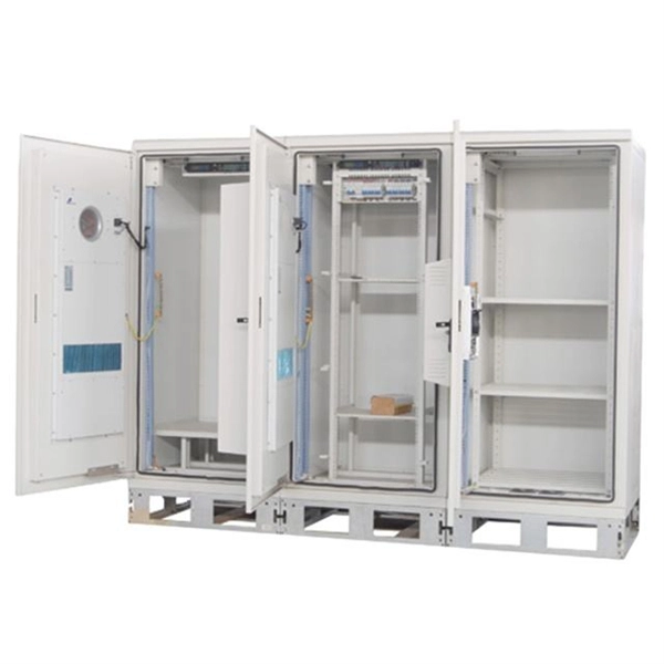
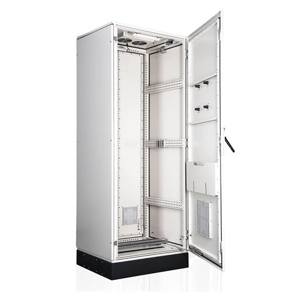
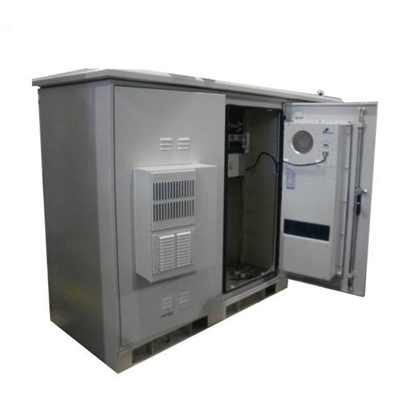
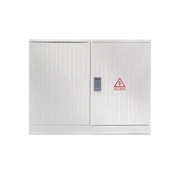
The XL-21 type low-voltage power distribution cabinet is an indoor fixed enclosed complete set of equipment that complies with IEC 60439-1 and GB 7251. It is specially designed for 50Hz AC power distribution systems with a rated voltage of 380V/660V and a rated current of. Standard Type (P Type): This version has a cabinet height of 1700mm or 1800mm and is designed for independent installation. It can be equipped with entry and exit holes at the top as required. Busbar Type (M Type): This version features a cabinet height of 1900mm or more, with a removable cover on. The Fulleto XL-21 series is an indoor, floor-standing power distribution cabinet engineered for excellence. It serves as the central hub for receiving and distributing electrical energy in low-voltage systems up to 380V. Designed for power plants, substations, industrial enterprises, and commercial. The XL-21 Power Distribution Box is used for power distribution, conversion, transmission, control, and on-site operations in low-voltage distribution systems. It is widely applied in power plants, substations, petroleum, chemical, metallurgy, machinery, and high-rise buildings. The XL-21 Power. The XL-21 type power distribution cabinet is a crucial component in electrical systems, designed to distribute power efficiently and safely across various industrial and commercial applications.
[PDF]
Customers close to a distribution transformer are able to have service drops directly connected to transformer secondary connections. Other customers are reached by routing a secondary main for servic.
[PDF]
Above finished grade or sidewalks, or from any platform or projection from which they might be reached. (If these areas are accessible to other than pedestrian traffic, then one of the other conditions applies). Ex: Parallel phase and neutral conductors can be installed in individual underground nonmetallic raceways (Phase A in raceway 1, Phase B in raceway 2, etc. ) as permitted by 300. 5 (I) Ex 2 if the installation complies with 300. Power conductors rated 1,000V or less can occupy the same. Switchboards and panelboards are often called “the guts” of a premises wiring system. Article 408 covers the requirements for switchboards and panelboards that control power and lighting circuits (Fig. For. According to the NEC, there are four types of branch circuits: 1. Appliance (2-wire circuit): Supply energy to one or more appliance outlets. They have not permanently connected luminaires unless these luminaires are part of the appliances – e., deep fryer, vacuum cleaner, toaster oven, coffee. The most common distribution primaries are f our-wire, multi-grounded systems: three-phase conductors plus a multigrounded neutral. Listed below are new code-related questions and.
[PDF]