This research report provides a comprehensive analysis of the Passive Optical Components market, focusing on the current trends, market dynamics, and future prospects. How does 6W market outlook report help businesses in making decisions? 6W monitors the market across 60+ countries Globally, publishing an annual market outlook report that analyses trends, key drivers, Size, Volume, Revenue, opportunities, and market segments. 22 USD Billion in 2024. The Passive Optical Component industry is projected to grow from 17. 01 USD Billion by 2035, exhibiting a compound annual growth rate (CAGR) of 6. 8% during the forecast period. Passive Optical Components are critical elements in fiber optic. Global passive optical component market is estimated to be valued at US$ 86. 2% from 2026 to 2033. Discover market dynamics shaping the industry: Download Free Sample Global passive. The Global Passive Optical Components Market was valued at USD 38. These components play a crucial role in the transmission of data, voice, and video signals over optical networks. The market for passive optical.
[PDF]
The main components include the light source, monochromator, sample holder, detector, and the output system, all of which work together to measure light across various wavelengths. The light source provides the energy necessary for the spectrometer to function. It typically emits light across a. While component types and devices vary from brand to brand, the core principle of how a spectrophotometer works stays largely the same. Listed below are some of the key components that make measuring transmittance possible. Figure 1: Components of a spectrophotometer: Light emitted from the source. Spectrometers are powerful instruments used to analyze the properties of light and matter, making them indispensable tools in various fields, including chemistry, physics, biology, and environmental science. They allow researchers and scientists to identify the composition of substances, measure. Wavelength selector is a component used to select and isolate the required wavelengths or range of wavelengths where the analyte is the only absorbing species (to obtain a certain wavelength or a narrow band of wavelengths). I will explain the principle as it applies to solid samples and solution samples separately.
[PDF]
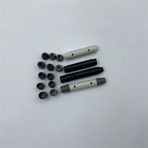
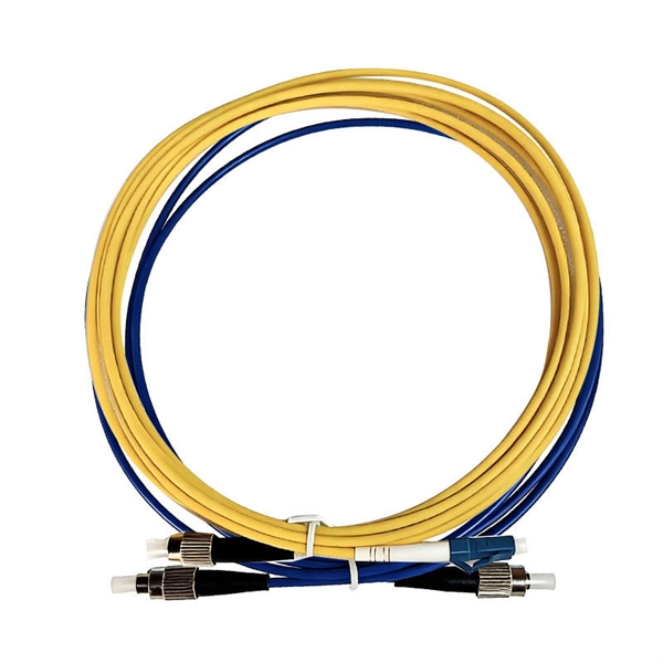
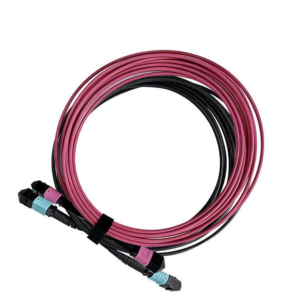
pigtails can be divided into single-mode (colored yellow) and multimode (colored orange) fiber. Multimode pigtails use 62.5/125 micron or 50/125 micron bulk multimode fiber cables and terminated them with multimode fiber optic c. pigtails can be divided into single-mode (colored yellow) and multimode (colored orange) fiber. Multimode pigtails use 62.5/125 micron or 50/125 micron bulk multimode fiber cables and terminated them with multimode fiber optic connectors at one end. 10G multimode fiber cables (OM3 or OM4) are also available in optic pigtails. The jacket color of 10. Fiber Optic Pigtails, In fiber optic cable installation, how cables are attached to the system is vital to the success of network. If done properly, optical signals would pass through the link with low attenuation and little return loss. pigtail offers an optimal way to joint optical fiber, which is used in 99% of single-mode applications. This pos. According to different types of pigtail cable connector terminated at the end, there are LC fiber pigtail, SC pigtail, ST pigtail, FC pigtail, fiber pigtail and so on. With different structures and appearance, each of them has their own advantages in different applications and systems. Let's go through some widely used ones. SC Pigtail: SC pigtail.
[PDF]
As illustrated in typical SFP internal structure diagrams, the module's core components include an optical transmitter assembly (TOSA), laser driver, optical receiver assembly (ROSA)—some high-sensitivity modules (like L16. 2) use APD receivers, which require an additional booster. As a key element in optical communication systems, optical transceivers serve as media between network devices to transmit and receive data. There has been lots of articles and guides on transceiver modules in the perspective of the package type while only a few of them cover the internal elements. Optical modules are devices used to connect network devices, transmit and receive data between network devices, and can be used to convert optical and electrical signals. The optical module is a very important component in an optical communication system. When you remove the metal housing of the optical transceiver, you will find that the internal components are connected to each other. The following section will focus on. In the era of 5G, AI, and high-speed data centers, optical modules serve as the core bridge for converting electrical signals to optical signals (and vice versa), enabling fast, reliable data transmission across networks. Among various optical module form factors, SFP (Small Form-Factor Pluggable). The optical transceiver module is mainly composed of three parts: housing, optical device and integrated circuit board. The following section will focus on.
[PDF]
Using OptiSystem software, we evaluated AWG performance in both multiplexer (MUX) and demultiplexer (DEMUX) configurations within the C-band (1530-1565 nm), analyzing key parameters including insertion loss (1. 4 dB), channel crosstalk (-32±2 dB), polarization-dependent loss. Array waveguide gratings (AWGs) have been widely used in multi-purpose and multi-functional integrated photonic devices for Microwave photonics (MWP) systems. In this paper, we compare the effect of output waveguide configurations on the performance of AWGs. The AWG with an output waveguide. Arrayed waveguide gratings (AWGs) are key optical components of various new applications in telecommunication, astrology, medical imaging, and spectroscopy. This study presents a comprehensive performance analysis and design optimization of AWG-based. A high-performance silicon arrayed-waveguide grating (AWG) with 0. 4-nm channel spacing for dense wavelength-division multiplexing systems is designed and realized successfully. The device design involves broadening the arrayed waveguides far beyond the single-mode regime, which minimizes random.
[PDF]
Polarization dependent loss (PDL) is a measure of the peak-to-peak difference in transmission of an optical component or system across all possible states of polarization. It is the ratio of the maximum and minimum transmission of an optical device with respect to all polarization. The determination of polarization dependent loss has become a stan-dard measurement when character-izing passive optical components. In optical networks, where polarization is not constrained and changes randomly, the PDL of components can accumulate in an uncontrolled manner. This effect can. arch, and 3) Matrix measurements using Mueller or Jones matrices. Each method has its own advantages and disadvantages in terms of measuremen ice under test (DUT) while the DUT's output power is monitored. The built-in motor con-trolled PDLE units have low insertion loss, low backreflection, low PMD and flat wavelength response. This. This is the authors' extended version of an article that has been published in Proc. 21th ITG-Symposium on Photonic Networks, ISBN 978-3-8007-5424-3. The final version of record is available at https://www. de/buecher/455423/itg-fb-294-photonische-netze. Abstract—A number. Abstract—State-of-the-art polarimeter calibration is reviewed. Producing many quasi-random polarization states and moving/bending a fiber without changing power allows finding a polarimeter calibration where the degree-of-polarization reaches unity and parasitic polarization-dependent loss is.
[PDF]
It discusses the key features, benefits, and applications of GPON SFP modules, highlighting their compatibility with GPON networks and their ability to support gigabit data transmission. Published: 2026 | Category: Network Hardware Knowledge Base / Optical Communications Core Keywords: SFP Module, SFP Transceiver, Small Form Factor Pluggable, What is SFP, SFP vs SFP+ Read Time: Approx. 25 Minutes Even in the era of Wi-Fi 7 and 5G, Optical Transceivers remain the backbone of the. An SFP (Small Form-factor Pluggable) is a compact, hot-pluggable transceiver module that allows networking equipment — including switches, routers, servers, and media converters — to support different physical media, such as optical fiber or copper, without replacing the host hardware. This modular. From gigabit Ethernet to 800G AI data center backbones — discover how SFP technology has evolved into the most critical component in global connectivity infrastructure. When selecting SFP cables, you'll encounter two main categories: passive and active. While both connect devices over fiber. A small form-factor pluggable, or SFP optic module, helps connect network devices fast. You can use an SFP optic module to turn electrical signals into optical signals. This lets you send data far away. But what is an SFP module exactly, and how does it work? In this guide, we'll break down what an SFP is.
[PDF]
This article explores how SFP modules fit into GPON FTTH, the key specifications to consider, practical deployment tips, and common pitfalls to avoid. We and our partners, including Shopify, use cookies and other technologies to personalize your experience, show you ads, and perform analytics, and we will not use cookies or other technologies for these purposes unless you accept them. Learn more in our Privacy Policy Precision optical solutions. SFP (Small Form-factor Pluggable) modules play a critical role in high-speed data transmission across enterprise, data center, and telecom networks. While these hot-swappable optical transceivers are designed for flexibility and performance, improper handling or lack of maintenance can lead to. Have you ever experienced an unexpected network outage due to the failure of an SFP/SFP+ optical transceiver? Network outages can bring your ability to communicate and work to a halt, and your IT team will likely be frantically looking for a solution. Attenuation (loss of light) is increased by contamination. Therefore, attenuation should be kept below 0. Follow these maintenance. ◦ Enable end users and partners familiar with traditional Ethernet LANs to understand Passive Optical Networks (PONs) ◦ Explain Cisco's and Panduit's position on PONs ◦ Describe PON components, application standards, considerations and guidance, and specification requirements ◦ Design ◦ Cabling ●.
[PDF]
1 × 8 and 1 × 16 traditional/saddle arrayed waveguide grating (AWG) devices with different core layer materials applied in fiber Bragg grating (FBG) system were designed, fabricated and compared. We ap.
[PDF]
Choosing between single-mode and multi-mode optical fiber shapes the performance ceiling of every high-bandwidth industrial sensing network. This guide maps the key technical distinctions, applicable standards, and the most productive research directions for. Optical fibers are among the most transformative technologies in modern photonics, quietly enabling the global internet, precision sensing, minimally invasive medicine, and high-power industrial laser systems. The. Discover ROI-boosting fiber choices: Single Mode vs Multimode Fiber. Get the right speed & savings for your network—download our guide for free today! Understanding the physics behind Single Mode vs Multi‑Mode Fiber is essential for selecting the right conduit for any optical network. Single‑mode. Choosing single mode or multi-mode installation is unquestionably one of the most crucial decisions. Understanding the distinctions between these two kinds of fiber glass are crucial since it will have a significant impact on your network's range, bandwidth, and spending. Single mode means the. Optical fiber cable transmits data as light at speeds exceeding 100 Gbps, far surpassing the 10 Gbps capabilities of legacy Cat 6A copper cable. Additionally, optical fibers support significantly higher bandwidths over greater distances without signal degradation. While both use light to transmit data, they differ fundamentally in core structure and how light travels.
[PDF]
A WaveSmart ® wavelength division multiplexer increases fiber capacity by combining or separating multiple wavelengths over a single fiber. Use of a WDM will replace the need to add more fiber cable in th.
[PDF]