This paper aims to study the design, simulation, and optimization of low-loss Y-branch passive optical splitters up to 64 output ports for telecommunication applications. For a waveguide channel profile, the standard material silica-on-silicon is used. Two important technologies for optical layer monitoring are Optical Performance Monitoring (OPM) and Optical Power Detection (OPD). Although they aim to maintain network health, they differ significantly in scope, technique, and deployment. This article delves into these differences, equipping. Optical Performance Monitoring (OPM) is considered a necessity over an optical network to enable sensibility of traffic line status and attain outstanding Quality-of-Service (QoS). The Y-splitters are designed and simulated at. Passive optical networks (PONs) are the network architecture of choice for residential fiber deployments. A PON is designed specifically to be cost-effective for delivering high data-rates to large customer populations. signals and various components of OPM functionalities are indispensable robust network operation and plays a key role flexibility and improve overall. Optical performance monitoring (OPM) is used for managing high capacity dense wavelength-division multiplexing (DWDM) optical transmission and switching systems in Next Generation Networks (NGN). OPM involves assessing the quality of data channel by measuring its optical characteristics without.
[PDF]
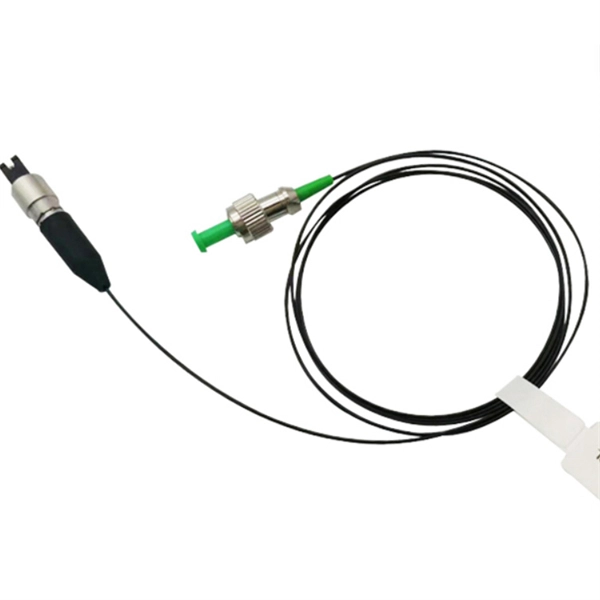
Insertion Loss (IL): Measures the amount of optical power lost at a connection point, typically expressed in decibels (dB). A lower IL value indicates better performance. designed for diverse fiber optic applications. But what exactly sets a fibe optic connector apart in terms of its merits? The primary purpose of a fiber optic connector is to terminate the ends of fiber optic cables, ensuring they can be int rconnected reliably with minimal optical loss. After. Optocouplers, also known as opto-isolators, are components that transfer electrical signals between two isolated circuits by using infrared light. As an isolator, an optocoupler can prevent high voltages from affecting the side of the circuit receiving the signal. Transferring signals over a light. Optical connectors are used to connect optical devices to other optical devices or systems. However, each connection introduces a certain amount of insertion and return loss that. When measuring the attenuation effects of the fiber connectors, insertion loss (IL) and return loss (RL) are two essential parameter measurements. While many factors influence these losses, the type of fiber optic connector used plays a crucial role. This article explores various connector types—such as SC, LC, FC, ST.
[PDF]
Choosing between single-mode and multi-mode optical fiber shapes the performance ceiling of every high-bandwidth industrial sensing network. This guide maps the key technical distinctions, applicable standards, and the most productive research directions for. Optical fibers are among the most transformative technologies in modern photonics, quietly enabling the global internet, precision sensing, minimally invasive medicine, and high-power industrial laser systems. The. Discover ROI-boosting fiber choices: Single Mode vs Multimode Fiber. Get the right speed & savings for your network—download our guide for free today! Understanding the physics behind Single Mode vs Multi‑Mode Fiber is essential for selecting the right conduit for any optical network. Single‑mode. Choosing single mode or multi-mode installation is unquestionably one of the most crucial decisions. Understanding the distinctions between these two kinds of fiber glass are crucial since it will have a significant impact on your network's range, bandwidth, and spending. Single mode means the. Optical fiber cable transmits data as light at speeds exceeding 100 Gbps, far surpassing the 10 Gbps capabilities of legacy Cat 6A copper cable. Additionally, optical fibers support significantly higher bandwidths over greater distances without signal degradation. While both use light to transmit data, they differ fundamentally in core structure and how light travels.
[PDF]
The key to choosing the appropriate one is to understand the theory on which each operates and the application that the attenuator will be applied to. Of course, you also need to be able to determine the attenuator value in decibels required for your application. Later in this article, we will discuss about the various advantages, disadvantages and application of attenuation. What is Attenuation? How Attenuation can be Prevented? What is Attenuation? Attenuation is a term in communication that refers to loss (reduction) in signal strength when a signal is. An optical attenuator, or fiber optic attenuator, is a device used to reduce the power level of an optical signal, either in free space or in an optical fiber. The basic types of optical attenuators are fixed, step-wise variable, and continuously variable. Optical attenuators are commonly used in. Fiber-optic attenuators are a specific type of optical attenuators which are used in fiber optics, e. for achieving a suitable signal level for a data receiver in a telecom system. Usually, such attenuators either have a housing equipped with some type of fiber connectors (e. The attenuator circuit will allow a known source of power to be reduced by a predetermined factor, which is usually expressed as decibels. Signal levels must be strong enough for data interpretation but not so strong as to damage the circuits in the receiver. Excessive fiber optic signal strength exceeding.
[PDF]
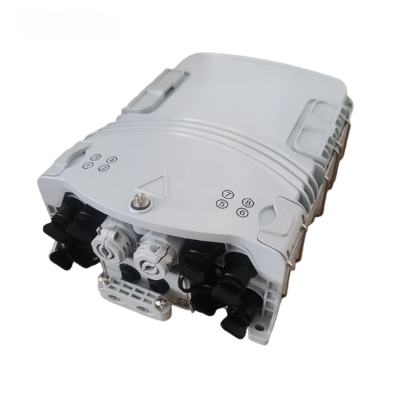
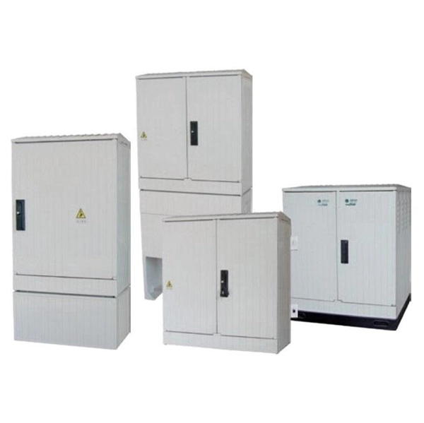
This white paper introduces an evolved methodology to manage FTTx Optical Distribution Network (ODN) performance. A centralized OTDR-based solution is the core of this evolved methodology, which greatly improves the visibility and operation efficiency in maintaining ODN . In recent years, optical network systems have doubled their information rate using a new multiplexing technique known as the Orbital Angular Momentum (OAM) of light, which gives signal carriers additional freedom. By utilizing new, sophisticated modulation formats and various access strategies. ODN footprints are exploding with FTTx, 5G back/fronthaul, and data-center access. Traditional maintenance—handwritten labels, scattered spreadsheets, and single-purpose tools—struggles with slow fault localization and unreliable records. On a. EXFO's remote fiber testing & monitoring solutions are built based on fixed OTDR test equipment placed at strategic central locations across the network. The condition of fiber optic installations are constantly checked and the locations of degradations or breaks are pinpointed within minutes of. The architecture of an optical distribution network (ODN) plays a pivotal role in determining the cost, scalability, and operational efficiency of PON and FTTx deployments. From dense urban builds to remote rural rollouts, this article compares three fundamental ODN structures to guide the design.
[PDF]
This paper has clarified comparative analysis of high index core micro structured optical fibers (HIMSOF) and hollow core band gap fibers (HCBGF) performance efficiency in the fiber communication system. Hollow-core optical fibers (HCFs) have unique properties like low latency, negligible optical nonlinearity, wide low-loss spectrum, up to 2100 nm, the ability to carry high power, and potentially lower loss then solid-core single-mode fibers (SMFs). These features make them very promising for. 10. 9 km Hollow Core Double Nested Antiresonant Nodeless Fiber (DNANF) with 0. 33dB/km loss at 850nm Abubakar I. Hassan, Yong Chen, Eric Numkam Fokoua, Marcelo Alonso, Hesham Sakr, David J. Richardson, Francesco Poletti, and Marco N. Ramkumar, Govindaraj, Rajasekaran, Vinodhini, Sivaraman, Deepa, Arumugam, Sivakumar, Praveena, Hirald Dwaraka, Prathima, Samuda and Zahran, Ahmed Ali. Hollow-core anti-resonant fiber (HC-ARF) has attracted considerable attention as an ideal optical transmission medium with great potential in. Adamu, Abubakar I., Hassan, Muhammad R. In Optical Fiber. Multimode fiber optic cable (or glass) is a common specification of optical fiber that offers a much wider core size or core diameter of 50-62. 5 microns (µm) compared to the 9 microns (µm) core diameter of single-mode fiber. Multimode fiber typically operates at a wavelength of 850 nm as it allows.
[PDF]
This article provides an in-depth exploration of OSFP copper cable technologies, including DAC, ACC, and AEC, with a focus on 400GB NDR splitter cable applications. Whether the signal is propagated by copper wire, optical fiber, Wi-Fi, or just yelling at the kids down the street, the signal is never as strong at the destination as it is at the source. In the case of physical voice communication, the kids will understand you if they are close-by. If they are. Insertion loss and attenuation are similar concepts, but one is assigned to a single component (insertion loss) whereas the other is assigned to generalized performance (attenuation). Both terms refer to a measurement comparing the signal strength received against a transmitted signal. Standard. Channel Master TV splitters are designed to equally divide the signals on the input port of the splitter to each of the output ports of the splitter. This. Insertion loss is the amount of energy that a signal loses as it travels along a cable link. It is a natural phenomenon that occurs for any type of transmission—whether it's electricity or data. This reduction of signal, also called attenuation, is directly related to the length of a cable—the. In fiber-optic networks like FTTx and PON, PLC splitters are key components for distributing optical signals to multiple users. However, each splitter has complex parameters, including insertion loss, return loss, polarization-dependent loss, and uniformity.
[PDF]