of relay protection coordination for a PV power plant connected to the distribution network is presented. In recent years, installation of PV power plants in the distribution network has increased significantly. I.
[PDF]
The article provides an overview of protective relaying principles and their applications for high-voltage power system components. It covers the protection methods for generators, transformers, buses, and transmission lines using various relay types to detect and. Protective relaying is the backbone of fault detection and system isolation in As transmission systems grow increasingly complex with integration of renewables and smart technologies, the design, configuration, and application of protective relays have become more critical than ever. This article. tensify their search for reductions in capital investment and operating expenses. Faced with the continuing demand for more and more power in an environmentalist era, many operating companies are seeking, among other things, a means for supplying eliable power with fewer transmission lines and. SIPROTEC 7SD82 provides compact, cost-optimized line differential protection for medium- and high-voltage systems. It ensures safety with 3-pole tripping in 19 ms and high availability via conformal coating. The modular SIPROTEC 7SD86 is specifically designed for line differential protection of. Still deciding? Get samples first! Order sample Still deciding? Get samples first! Order sample. In HV (High Voltage) and MV (Medium Voltage) substations, relay protection safeguards critical assets such as transformers, circuit breakers, and lines. Effective relay protection depends on.
[PDF]
The relay block comprises the two protection units, phase protection unit and earth protection unit. When the value of the current in any of the phases is greater than the pick up value, the phase protecti.
[PDF]

One-line diagrams and detailed network data (lines, transformers, buses). Short-circuit models, including fault current calculations under various system configurations. Protective relay settings and coordination curves. Historical. presentation of protection and control relaying. The report will identify methodology behind these practices, present issues raised by the integration of microprocessor relays and the internal logic and external communication configurations, ying. Schematic diagrams of protection relays are essential tools for power engineers in the power generation, transmission, and distribution industry. This includes AC schematics and DC schematics and diagrams that prominently feature relaying. There are other equally important types of drawings that are not the subject. Power System Protective Relays: Principles & Practices Presenter: Rasheek Rifaat, P. Eng, IEEE Life Fellow IEEE/IAS/I&CPSD Protection & Coordination WG Chair Jacobs Canada, Calgary, AB rasheek. com IEEE Southern Alberta Section PES/IAS Joint Chapter Technical Seminar - November 2016. Recognized under 2(f) and 12 (B) of UGC ACT 1956 (Affiliated to JNTUH, Hyderabad, Approved by AICTE - Accredited by NBA & NAAC – 'A' Grade - ISO 9001:2015 Certified) Maisammaguda, Dhulapally (Post Via. Kompally), Secunderabad – 500100, Telangana State, India To introduce all kinds of circuit.
[PDF]
Grounding of the units: Attach a ground wire from one of the threaded studs (A) at the bottom of the housing, to the mounting plate (B). The ground resistance between. This section applies to grounding of transmission and distribution lines and equipment for the purpose of protecting employees. Note to paragraph (a): This section covers. Learn what OSHA requires for electrical grounding in general industry and construction, and what violations can cost you. OSHA's grounding requirements are spelled out primarily in two sets of regulations: 29 CFR 1910 Subpart S for general industry workplaces, and 29 CFR 1926 Subpart K for. Power from factory ground must be installed by a qualified electrician. Each DISTRIBUTION BOX and controller must be grounded. On the US market, a 5. 26 mm 2 (10 AWG) ground wire must be used, and in all other markets a 6 mm 2 must be used. The lockout/tagout procedure must consider several factors, one of which is grounding. Sometimes, installing temporary protective grounding is necessary. Whether you're a seasoned pro or just starting out, this comprehensive guide will give you practical.
[PDF]
A Distribution Box, commonly known as a DB Box, serves as the central point for safely distributing electrical power from a main supply to multiple downstream circuits. It houses protective devices such as circuit breakers or fuses, ensuring both equipment protection and user. This ultimate guide explains what a distribution box does, its internal components, common types, real-world applications, and how to select the right DB Box for your project. We also highlight how reliable manufacturers like NUOMAK support stable, compliant, and cost-effective power distribution. At the heart of this network lies a power distribution box, the component responsible for dividing and controlling electricity as it moves from the main source to multiple end-use circuits. Within larger systems, the box often works in tandem with a distribution board, ensuring each circuit branch. A power distribution box is a key part of any electrical system. It takes electricity from the main source and safely sends it to different circuits in a home, office, or industrial setup. Without it, managing power would be messy, unsafe, and inefficient. But what exactly is a power distribution box, and why is it so essential in our daily lives? The DB panel board controls the flow of electricity. In the safe and effective supervision of electrical systems, distribution boxes may be the last quite unnoticed yet they are extremely fundamental part.
[PDF]
The Grid Code outlines the technical, planning and operational requirements for the installation, or modification, of Distributed Generation (DG) projects connecting to BL&P's Grid at 24. This document applies to all single-phase or three-phase DG facilities regardless. The Barbados Grid Code is split into different sections depending on the size of the generators. Planning Code for Generators ≤ 150 kW. Mini X-Treme Box temporary power distribution. 30A portable distribution box with duplex receptacles. (4) NEMA 5-20R 20A duplex straight-blade receptacles (8 total). Dedicated GFCI (ground fault circuit interrupter) module and circuit breaker for each pair of 20A receptacles. Engineered utilizing the latest in GFCI technology, Southwire's iconic yellow temporary power boxes have been providing contractors, electricians, and engineers with the highest level of electrical safety fo over 35 years. When combined with our specialty boxes and carts, Southwire.. Barbados power strips and PDU power distribution units for surface mount, rack mount and general purpose applications. Multiple outlet power strips are manufactured in accordance to Barbados standards with agency approvals.
[PDF]

The Multi-Purpose Drainage Catheter Pigtail is flexible tube made of polyurethane, intended for percutaneous introduction into two or more abdominothoracic anatomies (nephrostomy, biliary, abscess, pleural, peritoneal, mediastinal) [i., multi-purpose] for intermittent or long-term. If you are interested in our products You can send us an email at diamedical@163. com Zhengzhou DIALL Medical Technology Co. was founded in 2010, concentrate on making excellent brand of medical products. A pigtail catheter (PC) is a small, flexible chest tube that is commonly available in various sizes such as 6, 8, 8. 5, 10, 12, 14, 16, and 18 Fr. It is a less invasive alternative for pleural drainage as seen in a study of 109 consecutive 8. 3 French pigtail catheter placements. The. Introduction Traditionally, patients with pneumothoraces seen in the ED receive tube thoracostomy. However, in recent years, guidelines and statements from American College of Chest Physicians (ACCP) and British Thoracic Society (BTS) stress the value of observation, repeat imaging and prompt.
[PDF]
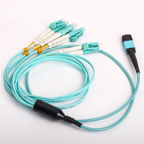
FBT splitters are more sensitive to fiber bending and environmental expansion, particularly under uneven thermal conditions. A beam splitter or beamsplitter is an optical device that splits a beam of light into a transmitted and a reflected beam. It is a crucial part of many optical experimental and measurement systems, such as interferometers, also finding widespread application in fibre optic telecommunications. a laser beam) into two (or sometimes more) beams, which may or may not have the same optical power (radiant flux). Different types of beam splitters exist, as described in the. Fiber optic splitters distribute optical power from one input fiber to multiple output fibers through either fused biconical taper (FBT) coupling or planar lightwave circuit (PLC) waveguide structures. Their performance depends on optical symmetry, waveguide integrity, and mechanical stability of. : The invention provides a light generating system (1000) comprising a first light generating device (110), a second light generating device (120), a luminescent material (200), a diffuser assembly (700), optical elements (500) comprising a first redirection optical element (1510), and a light exit. When splitting one incident light beam into two separate beams, beamsplitters are applied. Depending on the beam split based on intensity, wavelength, or polarization, its level of optical power on beam penetration differ. Just to mention few, these beamsplitter components are commonly required for.
[PDF]

Relay testing involves verifying the correct operation of protective relays under various fault conditions. This process ensures that the relays provide accurate and timely tripping signals to circuit breakers, isolating the faulty sections of the electrical network. Protective circuit functional testing, including lockout relay testing, must take place immediately upon installation, every 2 years thereafter, and upon any change in wiring. If applicable, documentation is required detailing how verified protection segments overlap to ensure there is not a gap. Relay systems protect high-voltage equipment and transmission lines to ensure safe, stable systems. Although failure of a protective relay system may have severe local or regional impacts, most protective relay systems are not required to operate to prove they are in working order. Ensuring that. Relay testing and maintenance are crucial aspects of ensuring the reliability and stability of power systems. Protective relays play a vital role in detecting and isolating faults in electrical networks, thereby safeguarding expensive equipment and preventing cascading failures. This guide provides recommended. Protective relaying aims to stop that chain reaction before it starts, detecting problems instantly, cutting off the affected section, and keeping the rest of the system stable and safe. A good preventive maintenance program ensures the protection system is in functioning order.
[PDF]
The top 5 companies shipping the most in 2023 remained CATL, BYD, EVE Energy, REPT BATTERO, and Hithium. CATL led with shipments exceeding 70 GWh. This article will introduce you to ten residential energy storage companies that have established themselves in the market with excellent products and solutions. Generac [FAQS. The power distribution unit (PDU) market in Haiti supports the countrys growing need for reliable power management solutions, especially in commercial and industrial sectors. This essential component plays a critical role in overall data centre management, as it provides centralised power management and improved uptime. Likewise, the PDU in data centre management can help. The top distribution box manufacturers in 2025 are SENTOP, Schneider Electric, Rockwell Automation, Hammond Manufacturing, Laiwo Electrical, J&HW Group, Siemens, ABB, Eaton, Legrand, and General Electric. These companies make rules for safety and performance. It is important to pick a reliable. Machinesequipments is a Power Distribution Equipment Manufacturers in Haiti, Power Distribution Equipment Haiti, Power Distribution Equipment Suppliers Haiti and Exporters in Haiti for Power Distribution Equipment. You can contact us by email at sales@machinesequipments. Multiple outlet power strips are manufactured in accordance to Haiti standards with agency approvals.
[PDF]
With key (included) turn the Earth lock clockwise (Fig 1). The Earth cover will pop open. Take the Earth cable end connector (not included) and plug into the Earth socket. The Powersafe connectors are mechanically keyed to prevent connection errors. In this video, the entire power distribution box is removed including electrical connections on the bottom. Enjoy kind human being of planet Earth. As for the opening of the equipment and the connection, see PDU INSTALLATION MANUAL (downloaded from www. This manual is developed for the. duct, please dispose the pro ormal operation due to poor manufacture quality. A paid repair will be provided if the warranty period expires. For any damage due to one of the following situations, a paid repair duct, please dispose the pro ype, a “R” is added after the Specification. It takes power from one source and spreads it out. PDUs are very important for managing power well. They are used in places like data centers and server rooms. 6 Earthing of power distribution box (optional) position, or to the green display (2) (dependent on the protective element). Close the inspection window. Ensure all connections are tight and secure. Look for any signs of burnt or damaged wiring. Testing Test the grounding system.
[PDF]
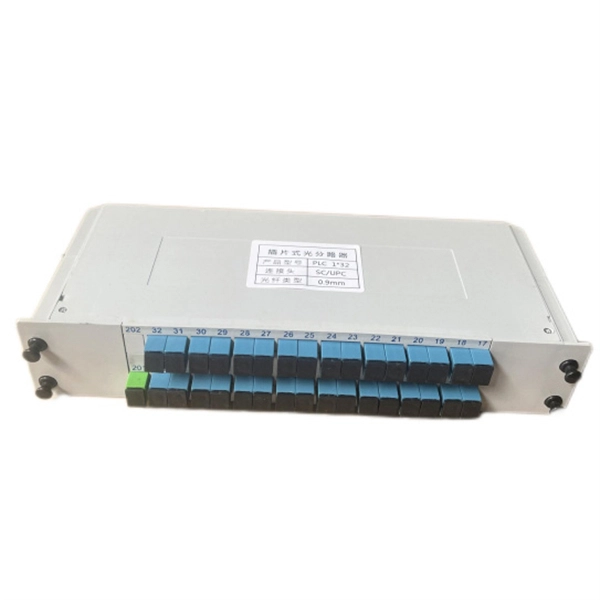
This paper aims to study the design, simulation, and optimization of low-loss Y-branch passive optical splitters up to 64 output ports for telecommunication applications. For a waveguide channel profile, the standard material silica-on-silicon is used. Two important technologies for optical layer monitoring are Optical Performance Monitoring (OPM) and Optical Power Detection (OPD). Although they aim to maintain network health, they differ significantly in scope, technique, and deployment. This article delves into these differences, equipping. Optical Performance Monitoring (OPM) is considered a necessity over an optical network to enable sensibility of traffic line status and attain outstanding Quality-of-Service (QoS). The Y-splitters are designed and simulated at. Passive optical networks (PONs) are the network architecture of choice for residential fiber deployments. A PON is designed specifically to be cost-effective for delivering high data-rates to large customer populations. signals and various components of OPM functionalities are indispensable robust network operation and plays a key role flexibility and improve overall. Optical performance monitoring (OPM) is used for managing high capacity dense wavelength-division multiplexing (DWDM) optical transmission and switching systems in Next Generation Networks (NGN). OPM involves assessing the quality of data channel by measuring its optical characteristics without.
[PDF]
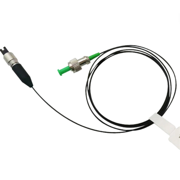
An optical power meter is an electronic device that measures the power of an optical signal. It helps engineers verify the performance of optical fiber systems, ensuring that the signal strength meets requirements, and is an essential tool for communication network maintenance and. An optical power meter (OPM) is a device used to measure the power in an optical signal. Other general purpose light power measuring devices are usually called radiometers, photometers, laser power meters (can be. An optical power meter (OPM) measures the power levels of light signals in devices that transmit data or power using light. The term "optical power meter" may sound generic, but in popular usage, it specifically implies a fiber optic power meter. For light power measurements outside the field of. Optical Power Meters (OPMs) are crucial instruments in the field of optical sensors and fiber optic communications. It provides an expert-curated supplier directory, buyer-focused technical background information, and structured selection criteria to support professional procurement decisions. It measures optical power directly, and it is also used in loss testing when paired with a stable light source.
[PDF]
Calculate power supply wattage by multiplying the total power consumption of all PC parts by 1. This article explains how to check CPU and GPU power usage, estimates for other components, the reason for multiplying by 1. 5, and introduces a calculation tool. Calculating the power supply unit's wattage may seem troublesome, but there is also a tool that calculates the power supply wattage just by selecting parts, so please use it. Modern systems draw power primarily from the CPU and GPU, with motherboards, memory, storage, and peripherals contributing smaller amounts to total system load. High-performance processors in 2026. Our advanced power calculator tool precisely calculates the wattage needed based on your selected components, ensuring optimal performance and compatibility. Select your components, get accurate power estimates, and find the right PSU with proper headroom and efficiency rating. It can be used to select a proper power supply unit for your system. It can also be used to calculate the cost of. Calculate your PC's exact power consumption and get instant PSU recommendations with safety headroom. Build with confidence using accurate TDP data for CPUs, GPUs, and all components. Stop guessing PSU wattage and avoid expensive mistakes.
[PDF]

