Relay testing involves verifying the correct operation of protective relays under various fault conditions. This process ensures that the relays provide accurate and timely tripping signals to circuit breakers, isolating the faulty sections of the electrical network. Protective circuit functional testing, including lockout relay testing, must take place immediately upon installation, every 2 years thereafter, and upon any change in wiring. If applicable, documentation is required detailing how verified protection segments overlap to ensure there is not a gap. Relay systems protect high-voltage equipment and transmission lines to ensure safe, stable systems. Although failure of a protective relay system may have severe local or regional impacts, most protective relay systems are not required to operate to prove they are in working order. Ensuring that. Relay testing and maintenance are crucial aspects of ensuring the reliability and stability of power systems. Protective relays play a vital role in detecting and isolating faults in electrical networks, thereby safeguarding expensive equipment and preventing cascading failures. This guide provides recommended. Protective relaying aims to stop that chain reaction before it starts, detecting problems instantly, cutting off the affected section, and keeping the rest of the system stable and safe. A good preventive maintenance program ensures the protection system is in functioning order.
[PDF]
Follow a clear step-by-step process: install the ground rod deeply, connect the grounding wire securely, attach it to the panel's ground bus bar, and test the system with proper equipment. Installed correctly, grounding wire can prevent electrical shocks or fires at homes or in offices. This guide reviews the basics of electrical grounding, how to safely ground wiring and how to check if wire is grounded. SHOP GROUNDING WIRES NOW Why Does Wiring Need to be Grounded? Install grounding. However, for experienced DIYers, this guide provides a detailed, step-by-step approach to ensuring your circuit breaker box is properly grounded, enhancing electrical safety grounding throughout your home. It. Section 250. For grounded systems, the NEC requires you to perform all of the following: electrical system grounding, electrical equipment grounding, electrical equipment. Drive a ground rod into the earth and attach a grounding wire to the main electrical panel to add grounding to an existing panel. Install new outlets with a continuous grounding connection to the grounding rod. In this post, I'll go through why every electrical panel should be grounded, what ground. The correct connection method of Distribution box grounding wire mainly includes the following steps: 1. Find the grounding bar or PE bar Open the distribution box and find the position marked with the grounding plate or PE letter.
[PDF]
In this video, we'll walk you through the process of wiring a home distribution box with a detailed connection diagram. Whether you're an electrician or a DIY enthusiast, this guide will help you understand the basics of home electrical distribution. more Welcome to our channel! In this video. Understanding the wiring diagram of an electrical panel box is essential for electricians and homeowners alike, as it allows them to troubleshoot any electrical issues, carry out repairs, or make additions to the system. The electrical panel box wiring diagram provides a visual representation of. A distribution board or distribution box is where the main power supply is distributed to multiple loads. And all the switching and protective devices are installed in the distribution box. Single Phase Distribution Box generally consists of Double Pole MCBs, Single Pole MCBs, and RCCBs. Connect the two hot conductors (typically black and red) to the line terminals of the main disconnect switch. Tighten each lug to 250 inch-pounds using a torque wrench. What is Distribution Board? Distribution board.
[PDF]
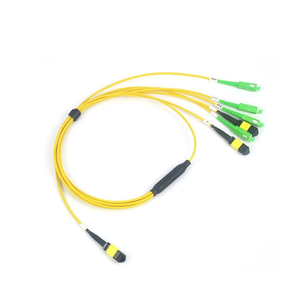
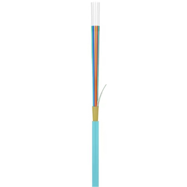
Stranded fiber optic cable is a loose tube made of high-modulus plastic by adding colored optical fiber and ointment at the same time, and the optical fiber can move in the tube. Different loose tubes are twisted along the central reinforcing core to make the cable core. A TOSLINK optical fiber cable with a clear jacket. These cables are used mainly for digital audio connections between devices. The cable core is added. A steel messenger is a stranded steel cable that acts lashing wire. This document describes further details of messenger strand, lashing wire, and the planning and installation process. Steel messenger strand consists. Fiber optic cables are used to transmit data and audio signals using light. They come in different types, each designed for specific applications and distances. This guide will help you identify the most common types of fiber optic cables and understand how many strands of fiber are typically found. Unlike copper wires, which are limited by lower data transmission speeds, shorter transmission distances, and higher susceptibility to electromagnetic interference, fiber optic cables offer unparalleled performance and can cover much greater distances without bumping up against signal degradation. Fiber optic "cable" refers to the complete assembly of fibers, other internal parts like buffer tubes, ripcords, stiffeners, strength members all included inside an outer protective covering called the jacket.
[PDF]
On the US market, a 5. 26 mm 2 (10 AWG) ground wire must be used, and in all other markets a 6 mm 2 must be used. Grounding of the units: Attach a ground wire from one of the threaded studs (A) at the bottom of the housing, to the mounting plate (B). Attach a second grounding wire from the mounting. The correct connection method of Distribution box grounding wire mainly includes the following steps: 1. Find the grounding bar or PE bar Open the distribution box and find the position marked with the grounding plate or PE letter. The basic rule achieves this through an equipment grounding jumper; four exceptions. An equipment grounding conductor passing through the box without a splice is not required to be joined inside the box to others that are spliced in the box. 148 addresses the continuity of equipment grounding conductors and their attachment in boxes. Not all boxes are metal or provide. Correct grounding of services depends upon understanding the definition and role of the grounded conductor. The neutral conductor is typically the grounded conductor connected to the system's neutral point, carrying current under normal operation. Whether you're a seasoned pro or just starting out, this comprehensive guide will give you practical.
[PDF]

This video shows real on-site footage of electrical installation, demonstrating safe and standardized wiring methods used by professionals. more Learn how to wire a distribution box step by step! This video shows real on-site footage of. A ddc panel wiring diagram provides a visual representation of the connections and wiring between the ddc panel and other components in the building automation system. It includes information about the various input and output points, the power supply, and the communication channels. A. A distribution box is the heart of any electrical system. It takes the incoming power and safely distributes it to different circuits throughout your building. Whether in a home or an industrial facility, this box keeps your electrical setup organized, functional, and efficient. This section will explain its function, types, and the importance of correct. A facility's direct digital controls (DDCs) form a living, breathing system that an owner will use throughout the life of the building. However, many control systems do not work as designed on “Day One,” much less after two to three years of use. Adding to the complexity are subcontractors, who. Strictly speaking, the word “Distribution Box (D-box)” can refer to two categories: electrical distribution boxes and septic tank distribution boxes. This article mainly talks about the first one. An electrical distribution box, also known as a power distribution box, panelboard, or consumer unit.
[PDF]
Each wire must connect to its appropriate terminal: Live wires (red or brown) connect to the MCB's live terminal. Neutral wires (black or blue) go to the neutral bus bar. Welcome to our channel! In this video, we'll walk you through the process of wiring a home distribution box with a detailed connection diagram. Whether you're an electrician or a DIY enthusiast, this guide will. This guide provides step-by-step instructions for connecting a distribution box and highlights key factors to consider during installation. What Is a Distribution Box? A distribution box, also known as an electrical distribution board, is a critical component in electrical systems. In Single Phase supply (230V in UK, EU and 120V & 240V in the US & Canada), there are two (one is Line (aka Phase, Hot or Live) and the other one is Neutral) incoming cables from the utility poles to the kWh energy. A distribution board or distribution box is where the main power supply is distributed to multiple loads. And all the switching and protective devices are installed in the distribution box. Single Phase Distribution Box generally consists of Double Pole MCBs, Single Pole MCBs, and RCCBs.
[PDF]
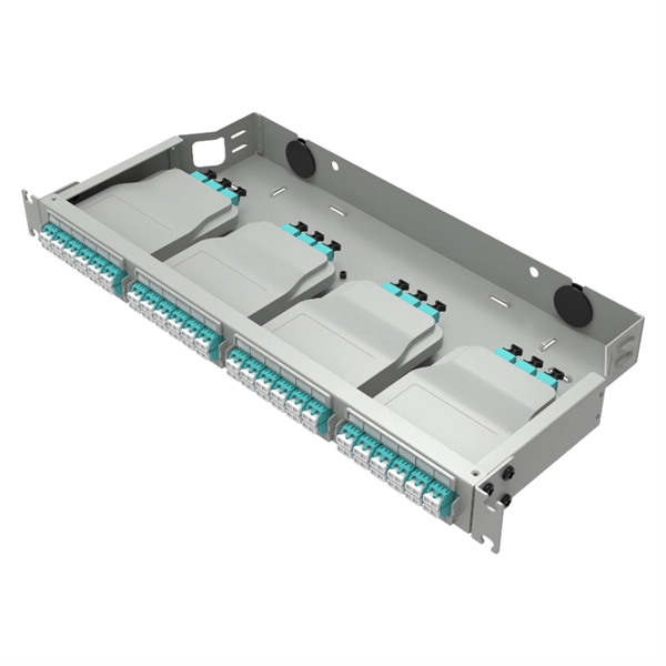
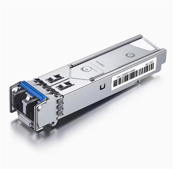
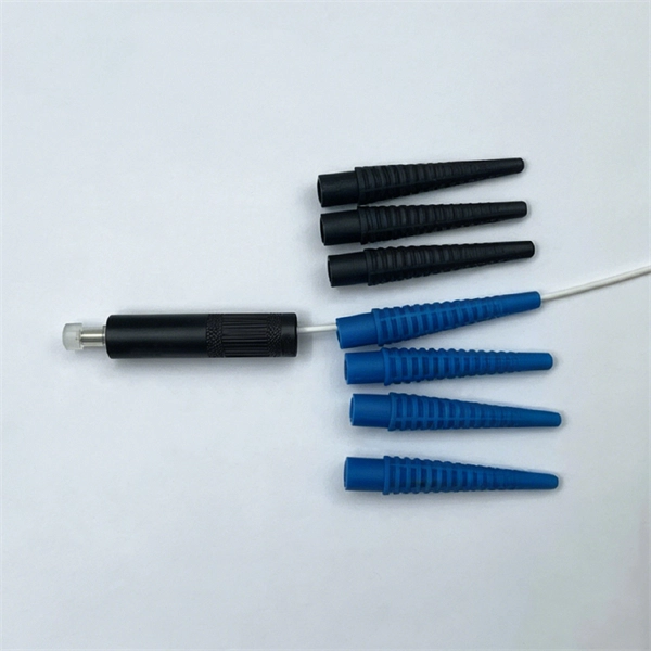
Proper fiber optic termination is a crucial process for ensuring the reliability, performance, and long-term durability of any fiber optic network. The process of fiber optic cable termination is the essential act of connecting fiber optic cables to devices, patch panels, or other. Fiber optic joints or terminations - where cables are terminated - are made two ways: 1) connectors that mate two fibers to create a temporary joint and/or connect the fiber to a piece of network gear (left) or 2) splices which create a permanent joint between the two fibers (right). Thus, you will put the cable across the points, stretch it to determine length, cut it accordingly, and place the connector on each end. After that, the patch panel attaches to it. Each cable has a connector attached. A. Once fiber optic cables have been successfully placed, we can focus on managing the ends of the fibers. This process depends on the project's needs and identifying a solution that aligns with the current situation. We can make suggestions that typically benefit the current circumstances and result. Where copper twisted pairs tend to terminate with an RJ45 plug, fiber optic connectors come in all sorts of shapes and sizes, with all manner of different use cases in mind. An optical fiber connector is used to join optical fibers where a connect/disconnect capability is required.
[PDF]
This post is a step-by-step detailed installation guide on how to run wires for security cameras to help you install security camera wiring for both indoors and outdoors. Proper wiring is crucial to ensuring that your security cameras function effectively and provide clear, uninterrupted footage. How to connect your cameras and recorder to provide power and a video feed, including for remote viewing via smartphones and computers. We always recommend wired systems when possible. We offer two different types of wired security camera systems -. There are two different ways to install security camera wiring: POE security camera wiring and wireless security camera wiring. Whether you're securing your home or business, the quality and installation of your camera wiring play a crucial role in ensuring consistent, high-quality video feeds. In this guide, we. This article provides a detailed principle explanation of 3R methods (reamplification, reshaping, and retiming) to reach the extension of passive optical networks. The second part of the article focuses on optical amplifiers, their advantages and disadvantages, deployment, and principles. We. In this step-by-step guide, we will walk you through the process of wiring your 2 wire security camera, providing you with a clear understanding of the necessary steps and a helpful diagram to refer to.
[PDF]
Where single conductor cables comprising each phase, neutral, or grounded conductor of an alternating-current circuit are connected in parallel as permitted in 310. Joining conductors in parallel is like having two or more smaller conductors connected at each end to make one larger conductor. The single input supply (phase and neutral) is connected to this main MCB. When this MCB is turned on all other MCBs will get the power supply. Single-pole MCBs are used for the output loads. The isolator is used to OPEN and CLOSE the lines manually, which is the main switch of the electrical system. The RCCB is a device used. These are usually connected to thick black or red wires, each carrying 120V in a split-phase system. Verify voltage with a multimeter: each line wire should show ~120V to neutral and ~240V across both hot wires. Load terminals, positioned below the line lugs, distribute current to downstream. What's a neutral?The IEEE defines a Neutral as the conductor that has an equal potential difference between it and all other conductors (hot wires). An example of a neutral wire would be the white/gray wire of a single-phase 120/240 volt system or a three-phase 4-wire Wye system, Figure 1-1. 10 (G) (2) through (G) (6).
[PDF]
This video shows real on-site footage of electrical installation, demonstrating safe and standardized wiring methods used by professionals. more Learn how to wire a distribution box step by step! This video shows real on-site footage of. Hey, in this article we are going to see the Single Phase Distribution Box Wiring Diagram and Connection Procedure. A distribution board or distribution box is where the main power supply is distributed to multiple loads. And all the switching and protective devices are installed in the. Box installation: Make sure that Distribution box has been correctly installed and fixed. Material preparation: Prepare the required circuit breakers, wires, wiring ties and other materials, and ensure that they meet the design drawings and installation requirements. Location determination:. In this video, we'll walk you through the process of wiring a home distribution box with a detailed connection diagram. Whether you're an electrician or a DIY enthusiast, this guide will help you understand the basics of home electrical distribution. What Is a Distribution Box? A distribution box, also known as an electrical distribution board, is a critical component in electrical systems. It serves as a.
[PDF]
This video shows real on-site footage of electrical installation, demonstrating safe and standardized wiring methods used by professionals. more Learn how to wire a distribution box step by step!. A distribution box, also known as an electrical distribution board, is a critical component in electrical systems. It serves as a central point for distributing electricity to various circuits in a building or facility. It has three categories: residential, commercial and industrial electrical distribution boxes, all of which play important roles in their respective electrical. In modern electrical systems, cable distribution boxes (also known as electrical distribution boxes or distribution boxes) play a crucial role as the key hub for managing, distributing, and protecting circuits. What is the role of the electrical panel? It's also called the breaker box or distribution board. It's the central hub that divides main service lines into smaller branch.
[PDF]
We have the equipment and personnel for the installation of the cable way system, Our national and international experiences in Costa Rica, México, Senegal, Mozambique, Camerún, Costa de Marfil, Ghana, Puerto Rico, Haití, República dominicana, Guatemala and others, have given. We have the equipment and personnel for the installation of the cable way system, Our national and international experiences in Costa Rica, México, Senegal, Mozambique, Camerún, Costa de Marfil, Ghana, Puerto Rico, Haití, República dominicana, Guatemala and others, have given. Costa Rica Phone — 011-506-2438-1980 Purchasing Email — purchasing@ticoelectronics. com Solicitud de Empleo Para oportunidades de empleo, haga clic aquí. This field is for validation purposes and should be left unchanged. With a $1 billion inventory of the industry's most trusted brands you can meet your quality and lead time demands right here. If you can't find what you're looking for, we're available to help. Costa Rica is the fifth largest Central American country with a population of almost five million. Traditionally, the country's major exports have been agriculture goods, such as coffee, sugar cane, pineapples and bananas; however, since the 1990s, manufacturing has made major in-roads into their.
[PDF]