What is the cost of a relay coordination study in Singapore ? The cost of a protective device study in Singapore depends on the complexity of the electrical system, facility size, and number of relays. I2R, as a firm of Professional Engineers and Licensed Electrical Workers, is qualified under the Electricity Act to carry out all types of electrical testing and commissioning works to ensure that electrical apparatus are fit for power energization and safe for use and operation. We have all the. We are Specialized in Low Voltage Switchgears Testing, Commissioning, Maintenance and Installations from OEM's. We do factory Acceptance and Site Acceptance Testing and Commissioning support of LV Switchgears. Earth loop impedance measurments. Care Offers cost-effective solutions for protective device coordination in compliance with. Advance Engineering and Testing (AET) Pte Ltd established on 2019, is a top provider of electrical testing ranging from commercial, domestic, and industrial. The company provides 24/7 onsite support with prioritization of customer satisfaction. Their vision and mission statement is to continuously. The type of testing required for each specific relay needs to be designed with the goal of accomplishing the objective. We perform testing in four specific classes which. Our services are applicable to a number of industries such as Petrochemical industries, Oil and gas fabrication industries, Wafer fabrication plants, Pharmaceuticals.
[PDF]

The standard industry practice is to set overload relays at 125% of the motor's nameplate Full Load Ampere (FLA) rating. Plug Setting Multiplier (PSM) indicates how many times the determined relay secondary current (typically the CT secondary) exceeds the relay pickup (plug) current. It is the key quantity utilized in IDMT (inverse definite minimum time) curves to calculate the basic operating time. PSM (Plug Setting. An overload relay is a crucial device for motor control, designed to prevent motors from overheating or suffering winding damage due to excessive current. Motor overload relays protect against sustained overcurrent conditions that cause dangerous overheating, insulation breakdown, and premature. Overload relays protect motors and equipment from thermal damage caused by prolonged overcurrent conditions. IEC 60255 defines standards, formulas, and performance requirements, enabling accurate calculations and real-world applications. How is the overload relay current calculated? Why include. Setting motor overload relays correctly is critical for protecting AC induction motors from sustained overcurrent conditions while avoiding nuisance trips during normal starting transients. This occurred when the relay F was set at 1. The complaint was that the relay tripped instantly on overload when the thermal damage curve show plotted for a specific current that was less t an.
[PDF]

A protection relay tripping circuit connects relays to breakers for fast fault isolation. Key components include trip/close coils and anti-pumping relays. Proper design, testing, and maintenance ensure reliable overcurrent, differential, and auto-reclosing protection in power. The protection relay tripping circuit refers to the critical electrical control loop that executes trip/close commands from protective relays to circuit breakers, ensuring rapid fault isolation in power systems. Essential. Electromechanical protective relays at a hydroelectric generating plant. The relays are in round glass cases. In electrical engineering, a protective relay is a relay device. A protective relay is an intelligent electrical device designed to detect faults in power systems and initiate corrective actions such as tripping a circuit breaker. Its main purpose is to safeguard electrical equipment like transformers, generators, and transmission lines from damage due to. By definition, a protective relay is a switchgear device that detects faults and initiates the circuit breaker operation to isolate the problematic component of the system. Electrical values are measured by these relays to determine abnormal circumferences of a circuit. It functions as a watchdog by constantly surveying multiple system components including voltage, current, frequency, and phase angle.
[PDF]
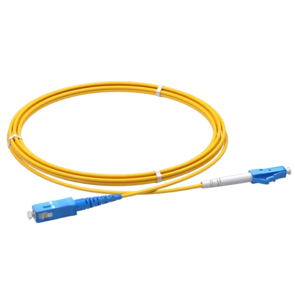
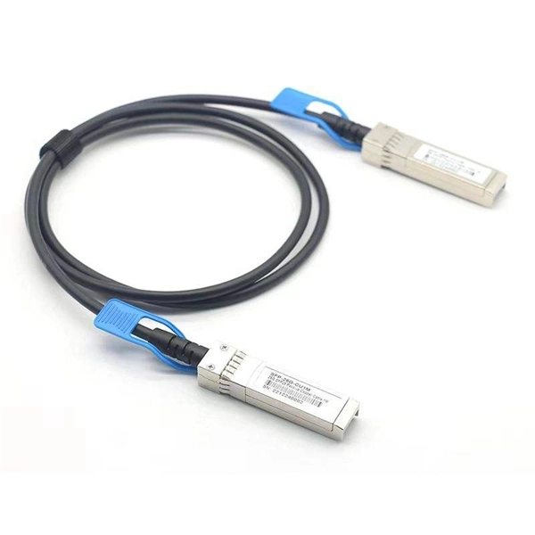
Temukan daftar Supplier, Pabrik, Importir, Distributor dan Toko Kabel Patch Cord untuk wilayah Indonesia . Update setiap hari, harga kompetitif dan layanan terpercaya. High performance and high quality connectors cable assembly are required for next generation optical networks to assure long term reliability for demanding applications such as FTTx, DWDM, 100G, CATV and etc. The connector assemblies are IEC, Telcordia and RoHS compliant. The termination passed. Prima Akses Digital Indonesia, is a Indonesian local company specialized in fiber optic product development and solution service for network infrastructure. Prima Akses Digital Indonesia, established in 2020, is supported by several partner companies and management which have been experienced in.
[PDF]
Relays may be fitted with a "target" or "flag" unit, which is released when the relay operates, to display a distinctive colored signal when the relay has tripped.OverviewIn, a protective relay is a device designed to trip a when a is detected. The first protective relays were electromagnetic devices, relying on coils operating on moving par. Electromechanical protective relays operate by either, or. Unlike switching type electromechanical with fixed and usually ill-defined operating voltage thresholds. Electromechanical relays can be classified into several different types as follows: "Armature"-type relays have a pivoted lever supported on a hinge or knife-edge pivot, which carries a moving contact. These relays may.
[PDF]
The article provides an overview of protective relaying principles and their applications for high-voltage power system components. It covers the protection methods for generators, transformers, buses, and transmission lines using various relay types to detect and. Protective relaying is the backbone of fault detection and system isolation in As transmission systems grow increasingly complex with integration of renewables and smart technologies, the design, configuration, and application of protective relays have become more critical than ever. This article. tensify their search for reductions in capital investment and operating expenses. Faced with the continuing demand for more and more power in an environmentalist era, many operating companies are seeking, among other things, a means for supplying eliable power with fewer transmission lines and. SIPROTEC 7SD82 provides compact, cost-optimized line differential protection for medium- and high-voltage systems. It ensures safety with 3-pole tripping in 19 ms and high availability via conformal coating. The modular SIPROTEC 7SD86 is specifically designed for line differential protection of. Still deciding? Get samples first! Order sample Still deciding? Get samples first! Order sample. In HV (High Voltage) and MV (Medium Voltage) substations, relay protection safeguards critical assets such as transformers, circuit breakers, and lines. Effective relay protection depends on.
[PDF]
Protection is accomplished by application of a definite time overcurrent option. Current setting is greater than full load current but is lower than the motor starting current. Should a motor stall whilst running, or fail to start, due to excessive. When a motor starts, it can draw 6-8 times its full-load current for a brief period, creating significant challenges for circuit protection, voltage regulation, and system capacity planning. Understanding motor starting characteristics is essential for proper breaker sizing, motor protection relay. These time-overcurrent elements support the IEC and U. (IEEE) time-overcurrent characteristics. Electromechanical disc reset capabilities are provided for all time-overcurrent elements. protection and fault clearance in abnormal situations. The main features of the motor relay include thermal overload protection, motor start-up time supervision, locked rotor protec ion, and protection against too frequent motor starts. Addi ionally, differential protection can also be included. In order to prevent damage to the contactor, the maximum peak let-through current (Ip ) and maximum clearing energy (I2t) (amps2 seconds) of the fuse must be less than the equivalent ratings for the contactor. The clearing time and let-through characteristics of the fuse must be considered when.
[PDF]

The total interruption time for a modern high-voltage SF6 circuit breaker is typically between 40 to 60 milliseconds on a 50Hz grid, or 2 to 3 cycles. This is the total time from the trip signal to the final arc extinction, a critical parameter for grid safety. While knowing the total time is a. When a SF6 circuit breaker (CB) hits its critical low pressure, its fault interrupting capability can be compromised. Most TOs protect against this by either auto-opening the CB prior to reaching the critical low-pressure level or by blocking the CB from tripping (when it reaches the critical. The protected zone is defined and limited by different things depending on the protection function. Definite time delay means that the protection operate time dose not change or depend on the fault type or the fault current magnitude. Instead of oil, air, or a vacuum, a sulfur hexafluoride circuit breaker uses sulfur hexafluoride (SF 6) gas to cool and quench the. Page 1 Content Instruction Manual circuit- breaker GL317 With spring operating mechanisms FK3- 4 Administrator First issue Compiled by Approved by 19- 11- 2012 J. Texier Imagination at work Grid Solutions 04- 2017 D1736EN/03 GE Information 1/10. Page 2 Content Instruction Manual This. A comparison of the time it takes protective devices to operate when certain levels of normal or abnormal current pass through them. LV circuit breaker ratings.
[PDF]
With its novel and future-oriented approach our software solution for system-based protection testing, performs tests independent of relay type, relay manufacturer, and offers extensive parameter settings. It focuses on. With its novel and future-oriented approach our software solution for system-based protection testing, performs tests independent of relay type, relay manufacturer, and offers extensive parameter settings. It focuses on the correct behavior of the protection system by simulating realistic events in the power system. RelaySimTest. Specifically designed for settings-based protection testing with a high degree of automation, our modular software Test Universe offers numerous functions and application-optimized test modules that save you valuable time. Test Universe. Use CMControl P for quick and easy manual testing. CMControl P is available as an App for Android tablets and Windows PC, or as a dedicated front-end device. CMControl P. With this software the CMC test set becomes a multifunctional measurement and recording unit. You can use EnerLyzer in parallel with the software used for operating your CMC. Enerlyzer. The open programming interface CMEngine enables you to integrate the CMC test sets into your own testing environment and control them within any type of application. CMEngine.
[PDF]

The SEL-221F Relay uses positive-sequence memory voltage polarized mho distance elements for phase and ground distance protection. These elements expand in proportion to the source impedance to provide more resistive fault coverage than self-polarized mho elements. VAMP 221 arc protection system components. Central unit VAMP 221. I/O units VAM 12L / VAM 12 LD, VAM 10L / VAM 10LD, VAM 3L / VAM 3LX and VAM 4C / VAM 4CRL / VAM 4CD 10 1. Arc sensors VA 1 DA, VA 1 EH, ARC SLx. Schneider Electric VAMP range is an arc flash detection and protection pioneer offering fast and reliable devices to improve safety. VAMP 221 significantly reduces the risk of potential personal damage, and material and production losses caused by arc fault. VAMP 221 complies with the latest standards concerning the. Serial communications ports allow local or remote interaction with the relay. 5” high chassis sizes. The report will identify methodology behind these practices, present issues raised by the integration of microprocessor relays and the internal logic and external communication configurations, ying. In the design of electrical power systems, the ANSI Standard Device Numbers denote what features a protective device supports (such as a relay or circuit breaker).
[PDF]
Using a multimeter, check continuity between the black connector and the marked pin of the optocoupler input that is not working. If there is no continuity, the possible causes are: Connect a 5 V to 24 V signal to the input being tested. Measure the voltage at the marked. Using a multimeter, you can perform several tests to assess the functionality of an optocoupler. Each test targets a specific aspect of the optocoupler's operation. An optocoupler is an essential electronic component that transfers signals without a direct electrical connection. more n this video, you will learn how to test an optocoupler (optoisolator) using a. Optocoupler is one type of ICs, It isolates input and output section by using optical technology this feature increase safety of circuit. Optocoupler has many part number, different part number has different output type so before checking it has to use part number to research with datasheet and. If any optically isolated input on the controller is not working, follow the steps below to identify the cause. For our demo purposes, we will be using the PC817, a commonly used transistor output optocoupler in electronics. An opto-isolator contains a source (emitter) of light, almost always a near infrared light-emitting diode (LED), that converts electrical input signal into light, a closed optical channel (also called dielectrical channel, and a photo sensor, which detects incoming light and either generates.
[PDF]
Every protection system which isolates a faulty element is required to satisfy four basic requirements: (i) reliability; (ii) selectively; (iii) sensitivity; and (iv) speed of operation. Protection system is an extremely important part of the power system as it is provided to operate under abnormal conditions to prevent failure or isolate trouble and limit its effect. It is designed to detect and isolate faults or abnormal conditions within the system to prevent damage, minimize downtime, and maintain power quality. This. Relay protection primarily operates on the principle of utilizing the variations in electrical quantities (such as current, voltage, power, frequency, etc. It emphasizes selectivity, coordination, fault response, and system behavior rather than individual relay devices. Relay protection is often misunderstood as a. Protective relays and devices have been developed over 100 years ago to provide “lastline”of defense for the electrical systems. They are intended to quickly identify a fault and isolate it so the balance of the system continue to run under normal conditions. The selection and applications of. Abstract: Information on the concepts of protection of ac transmission lines is presented in this guide. Many important issues, such as coordination of settings, operating times, characteristics of.
[PDF]

One-line diagrams and detailed network data (lines, transformers, buses). Short-circuit models, including fault current calculations under various system configurations. Protective relay settings and coordination curves. Historical. presentation of protection and control relaying. The report will identify methodology behind these practices, present issues raised by the integration of microprocessor relays and the internal logic and external communication configurations, ying. Schematic diagrams of protection relays are essential tools for power engineers in the power generation, transmission, and distribution industry. This includes AC schematics and DC schematics and diagrams that prominently feature relaying. There are other equally important types of drawings that are not the subject. Power System Protective Relays: Principles & Practices Presenter: Rasheek Rifaat, P. Eng, IEEE Life Fellow IEEE/IAS/I&CPSD Protection & Coordination WG Chair Jacobs Canada, Calgary, AB rasheek. com IEEE Southern Alberta Section PES/IAS Joint Chapter Technical Seminar - November 2016. Recognized under 2(f) and 12 (B) of UGC ACT 1956 (Affiliated to JNTUH, Hyderabad, Approved by AICTE - Accredited by NBA & NAAC – 'A' Grade - ISO 9001:2015 Certified) Maisammaguda, Dhulapally (Post Via. Kompally), Secunderabad – 500100, Telangana State, India To introduce all kinds of circuit.
[PDF]
of relay protection coordination for a PV power plant connected to the distribution network is presented. In recent years, installation of PV power plants in the distribution network has increased significantly. I.
[PDF]
The document discusses the principles and philosophy of protective relaying in power systems, emphasizing its role in preventing equipment damage and improving system reliability. Following a review of power system equipment, students define common protection terms and use common IEEE device designations while performing acceptance tests on protective relay schemes and elements. Combined with logic statements and a breaker control scheme, students develop a coordinated. IEEE/IAS/I&CPSD Protection & Coordination WG Chair Jacobs Canada, Calgary, AB rasheek. com IEEE Southern Alberta Section PES/IAS Joint Chapter Technical Seminar - November 2016 Protective Relays - Technical Seminar Nov 2016 - Copyright: IEEE 2 Abstract: Protective relays and devices. Georgian DS is a station that is supplied from a 44 kV feeder with one 10. 0 MVA delta/wye transformer with Z=6. The rated voltage of the primary winding is 46. The Question: ELEC 3007 - Assignment 7 - Protection Co-ordination Study (50) Name: This assignment will involve the relay. The Multilin™ 8 Series platform of advanced protection and control relays delivers high quality and performance management, protection and control for transformer, generator, motor and feeder applications. It outlines the factors influencing protection schemes, the importance of designing systems for selectivity and speed.
[PDF]