Simple 3-phase distribution board wiring diagram for home use, showing safe connection of power supply, breakers, neutral, and earth for residential electrical systems. Hey, in this article we are going to see the Three (3) Phase Distribution Board Wiring Diagram and Connection Procedure. The three-phase distribution board is used to distribute power to the three-phase loads and circuits such as three-phase motors, three-phase machinery, three-phase to. In a newly constructed residential area, a 10kV power line is introduced into the substation. After stepping down the voltage through the transformer's low-voltage side (0. The following is a detailed introduction about it: - **First-level Distribution. Utilities may have some control over and access to the energy stored in electric vehicles attached to the grid. ndards and conformity assessment activities in the United States. ANSI facilitates and promotes voluntary consensus standar rty or economic loss due to fire, electrical and related hazards. They deliver information and knowledge through more than 300 consensus codes and nspection to protect people.
[PDF]
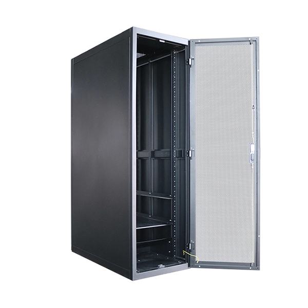
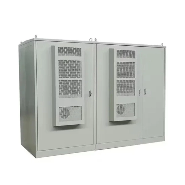
A server rack is a standardized metal enclosure designed to mount IT equipment—servers, switches, routers, PDUs, UPS systems, storage devices, patch panels, and cable managers—using vertical rails spaced according to the EIA-310 19-inch standard. What is a Server Rack? A server rack is specially designed to store various networking devices, which can effectively organize, manage, and protect network equipment including servers, network switches, routers, UPS, storage devices, etc., ensuring the stable and reliable operation of equipment. There are three primary rack types - open-frame racks, enclosed cabinets, and wall-mount racks, each suited for. The server rack is designed to house, organize and secure servers, networking equipment and other IT hardware. It provides efficient cable management, air flow and physical protection for sensitive electronic devices. Learn more about how airflow affects server performance in our detailed guide on how airflow works inside a. Hot and cold air containment systems designed to maximize cooling predictability, capacity, and efficiency at the rack, row or room level. Intelligent air containment solutions that protect critical IT equipment and personnel. Server racks come in a variety of sizes and configurations, ranging from small desktop units to large floor-standing.
[PDF]
Q: Is a network rack worth it for a home network? A: Absolutely. If you have more than just a modem and router—think a switch, NAS, patch panel, or UPS—a small wall-mount rack organizes and protects your investment, ensuring reliability. A networking rack, often referred to as an equipment rack, stands as a foundational component in the realm of network infrastructure. Crafted from durable metal, its primary role is to securely house and systematically organize a variety of networking devices. This setup is designed for. At some point, the question becomes practical rather than technical: do you actually need a server rack at home? The answer is not automatically yes. But it is also not limited to enterprise IT environments. The racks are typically made of steel or aluminum for durability and strength and are designed to be. While server racks are engineered to support mission-critical, heat-intensive computing environments, network racks prioritize cable routing, switch management, and patch panel accessibility. Learn more about how airflow affects server performance in our detailed guide on how airflow works inside a. If you're new to networking or wondering whether you need a network cabinet, this beginner's guide will help you understand what they are, how they work, and why they are more important than ever in 2025. These racks enable efficient space utilization, proper ventilation, and organized cable management—critical for maintaining reliable.
[PDF]
It can also describe a unit that is 1U high and half the depth of a 4-post rack (such as a network switch, router, KVM switch, or server), such that two units can be mounted in 1U of space (one mounted at the front of the rack and one at the rear).OverviewA rack unit (abbreviated U or RU) is a unit of measure defined as 1+3⁄4 inches (44.45 mm). It is most frequently used as a measurement of the overall height of, as well as the height of eq. The rack unit size is based on a standard rack specification as defined in -310. The specifies a standard rack unit as the unit of height; it also defines a similar unit, (HP), used to measure the width o. A typical full-size rack is 42U, which means it holds just over 6 feet (180 cm) of equipment, and a typical "half-height" rack is 18U–22U, which is around 3 feet (91 cm) high. The mounti.
[PDF]
This diagram highlights media converters, switches, and cable types. Also thanks to Init7 (for the great service), r/FiberOptics and FS for providing me with what I needed to get this setup going. If you find this article useful and you are considering Init7 as your provider you can use my referral code “20700408098” to get CHF 111. - off hardware and also support me. Keeping this page as a placeholder for now. Have any questions? Talk with us directly using LiveChat. A fiber optics network diagram illustrates how high-speed data travels from an internet service provider to end users. By using light signals, fiber optics provide faster speeds and better reliability than. MS Visio has long been the default choice for drafting fiber network diagrams, and with the right stencil libraries it can be used to draw everything from backbone routes to detailed patch panel layouts. When fiber techs look for visio fiber stencils, they are usually solving a very practical. Be among the first to receive important product updates, insights and news. Fiber optic cable is used for everything from demarcation point wiring to network signal distribution to video signal extension. Often, fiber enters the structure to a centralized rack or data room where it is connected to a modem. The modem connects to a network switch which connects each remote.
[PDF]

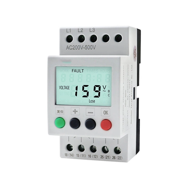
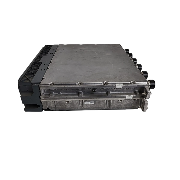
One-line diagrams and detailed network data (lines, transformers, buses). Short-circuit models, including fault current calculations under various system configurations. Protective relay settings and coordination curves. Historical. presentation of protection and control relaying. The report will identify methodology behind these practices, present issues raised by the integration of microprocessor relays and the internal logic and external communication configurations, ying. Schematic diagrams of protection relays are essential tools for power engineers in the power generation, transmission, and distribution industry. This includes AC schematics and DC schematics and diagrams that prominently feature relaying. There are other equally important types of drawings that are not the subject. Power System Protective Relays: Principles & Practices Presenter: Rasheek Rifaat, P. Eng, IEEE Life Fellow IEEE/IAS/I&CPSD Protection & Coordination WG Chair Jacobs Canada, Calgary, AB rasheek. com IEEE Southern Alberta Section PES/IAS Joint Chapter Technical Seminar - November 2016. Recognized under 2(f) and 12 (B) of UGC ACT 1956 (Affiliated to JNTUH, Hyderabad, Approved by AICTE - Accredited by NBA & NAAC – 'A' Grade - ISO 9001:2015 Certified) Maisammaguda, Dhulapally (Post Via. Kompally), Secunderabad – 500100, Telangana State, India To introduce all kinds of circuit.
[PDF]
Ever wondered how pigtail bolts—critical components in power line fittings—are made? Watch as we take you through the entire manufacturing process step by st. How to Make Electrical Pigtails: This is a basic tutorial on what electrical pigtails are and how to make them. Disclaimer: Always use multiple sources and do your homework before performing any electrical work. Also, make sure all work is done within national and local code. Let's look at how to make pigtail wire links below. Also, it can join several wires to become a single conductor for electrical connections. Let us suppose I had 14 shielded wires to bring into a 15-pin connector where only one pin was available for shield grounds. Imagine how fat a lump there will be if all the shield terminations are located right next to. Bulb to Socket & Component to Connector Cross Reference Guide des spirales de raccord et des douilles Renvois ampoules/douilles et composants/connecteurs Guía de cables flexibles y adaptadores Referencias a bombillas/adaptadores y componentes/conectores NAPA®ECHLIN IGNITION, EMISSION, ENGINE. Pigtail connections are most frequently used to ground a switch or electrical outlet and for electrical devices that need to connect to multiple circuit wires. They also come in handy to lengthen circuit wires that are too short to reach a device. A pigtail is composed of three strands of wire.
[PDF]
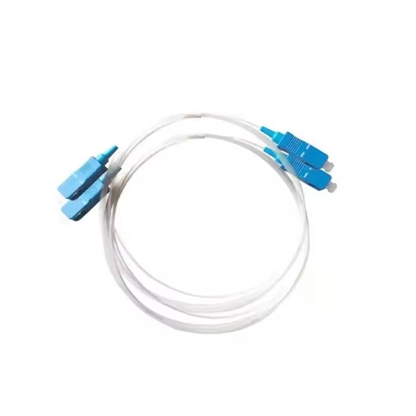
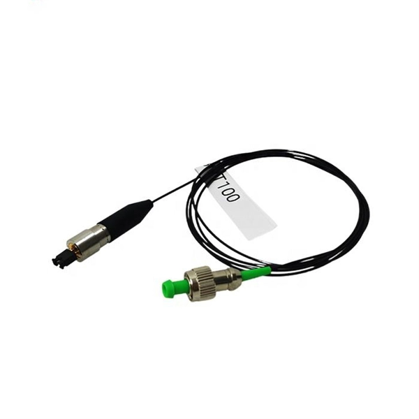
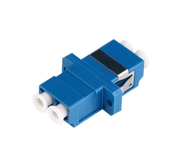
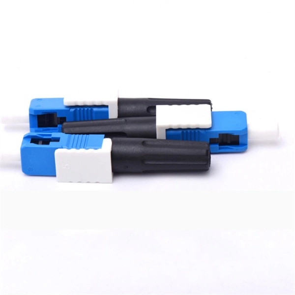
A fiber optic pigtail is a short length of optical fiber —typically 0. 5m to 2m—that has a factory-terminated connector on one end and bare fiber on the other end. The connector end is polished and tested under factory conditions, ensuring low insertion loss and high return loss. They are the bridge between fiber optic cables in the field and the equipment or patch panels that manage them. By combining factory-installed connectors with spliced bare fiber, pigtails ensure that network installers can create fast, reliable, and cost-effective terminations. Without pigtails. What is a Fiber Optic Pigtail, and What Is It Used For? Written by Ben Hamlitsch, trueCABLE Technical and Product Innovation Manager RCDD, FOI A fiber optic pigtail is a type of fiber optic cable with only one end that has a factory-terminated connector and the other end exposed as bare fiber. ) fitted on one end and the other end undressed (for connection through fusion or splicing) to the main fiber optic cable. It is usually suitable for field termination using a mechanical or fusion splicer. Compared with quick termination or epoxy and polish connections placed on the field. Fiber optic pigtail offers an optimal way to joint optical fiber, which is used in 99% of single-mode applications. This post contains some basic knowledge of fiber optic pigtail, including pigtail connector types, fiber pigtail classifications.
[PDF]
Roadside Telecommunications (RS-TC) Fiber Optic Cable Installation Adjusted Capital Cost Scatter Plot The data used to produce this cost plot are sourced from the ITS Sample Unit Costs Database. These cost data are obtained directly from a variety of sources. Buying fiber optic installation services involves several cost components, with total price influenced by length, location, and access. The main cost drivers include trenching or aerial deployment, materials, labor hours, and any required permits. This guide presents typical price ranges in USD to. Costs to run fiber optic cable vary by distance, trenching needs, cable type and labor rates. This guide outlines typical price ranges and what drives the total cost for U S buyers. Commercial building installations with 100-200 network drops generally range from $15,000 to $30,000. You should account for permit. Typically, per drop fiber cabling prices range from $250 – $1000 per drop depending on the type of fiber (OM2, OM3, OM4, or OM5), multi or single mode, PVC or plenum, average drop length, and also the number of fibers in each cable. Unit cost descriptions have not been.
[PDF]
Download a comprehensive set of Cable Tray Installation CAD Blocks in DWG format, ideal for electrical engineers, MEP designers, and industrial layout planners. This article shares simple ways to plan your cable trays and wiring. We want to help electrical engineers, technicians, and anyone working with electrical setups build safe and good systems. This collection includes installation details for ladder trays, perforated trays, solid-bottom trays, and wire mesh trays, along with. This guide provides step-by-step instructions on installing a cable tray on a wall, covering different types of cable trays, tools needed, and safety tips. The Ladder Tray features light, rugged, tubular steel construction. It is designed for. In industrial settings, electrical and instrumentation (E&I) cable trays or bridge racks play a critical role in organizing and supporting power, control, and signal cables across facilities. An effective layout ensures safety, minimizes interference, reduces maintenance time, and keeps the overall. ALL TO BE CLEANED WITH A COMMERCIALLY AVAILABLE CLEANSER PRIOR TO ALL MARKERS AFFIXED PRIOR TO INSTALLATION OF ANY CABLE. BONDING JUMPER SHALL BE INSTALLED FOR ELECTRICAL CONTINUITY ACROSS ALL DETAIL AT INTERFACES AND/OR CONDUIT BUSHINGS SHALL INSTALLED FCR ENTRY OF CABLES.
[PDF]
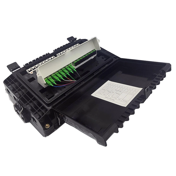
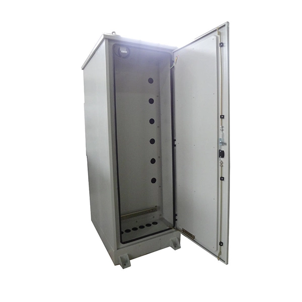
Grommet will be installed after the enclosure is mounted to the rack. Place the mounting brackets at the desired position on the rack. Note: Cover not. Page 1 Care should be taken when opening or closing a fully loaded drawer in order to protect the fiber components. ASSEMBLY VIEW Trunk or interconnect Enclosure cable entry location Fiber Adapter Panels (FAPs): Up to 4 for FCE1U & FCE1UA Up to 8 for FCE2U Strain relief (sold separately) bracket. Simple training video for our teams after pulling the fiber to locations, either the MDF or IDF spots. To secure the fiber and get it ready to splice for the pigtails. Keep in mind various methods or different trays to use, just depends on the layout but most should look like this. Protect the. This guide provides detailed installation steps and precautions to help users successfully install the slide-out rack mount enclosure, improving cabling efficiency and product application effectiveness. What's a Slide-Out Rack Mount Enclosure FS slide-out rack mount enclosure shall house, organize. Keeping this page as a placeholder for now. Have any questions? Talk with us directly using LiveChat. with eyes, flush with water for at least 15 minutes. When using isopropyl alcohol, always assure proper levels of ventilation. Enclosure for use in your equipment cabinet or rack. For detailed inform Opt-X UHD Enclosure, please refer to the table below. Use (2) #12-24 X 1/2" screws (provided). Repeat for other side.
[PDF]
A typical full-size rack is 42U, which means it holds just over 6 feet (180 cm) of equipment, and a typical "half-height" rack is 18U–22U, which is around 3 feet (91 cm) high. The mounting-hole distance (as shown to the right) differs for 19-inch racks and 23-inch racks: 19-inch racks use uneven spacings (as shown to the right) while 23-inch.
[PDF]
A rack unit, abbreviated as U (or RU), is a standardized unit of measurement used to describe the vertical space occupied by equipment in a server rack. 1 Rack Unit (1U) = 1. 45 millimeters) in height. This standardization allows IT equipment like servers, switches, routers, and patch. A “Rack Unit” (U) is a standard height measure for mounting equipment in a server rack. This article explains definition, planning, installation tips, and trends. When working with server racks or rack-mounted battery systems, you'll often come across the letter “U” or “RU”. 75 inches or three threaded, square or circle holes. This setup ensures that servers, switches, and storage devices can be installed in a consistent and compatible manner across several systems. A server rack also helps optimize space.
[PDF]
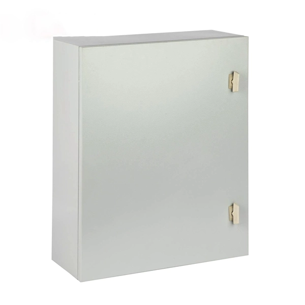
In this video, we'll walk you through the process of wiring a home distribution box with a detailed connection diagram. Whether you are an electrical contractor or a construction brigade, knowing how to properly and safely install distribution boxes is the basis of ensuring the safe operation of the entire system. This article details the process of installing them, which helps you comprehend distribution boxes. In modern electrical systems, cable distribution boxes (also known as electrical distribution boxes or distribution boxes) play a crucial role as the key hub for managing, distributing, and protecting circuits. Covers wiring, placement, standards, and expert tips for a compliant setup. A distribution box is the heart of any electrical system. It takes the incoming power and safely distributes it to different circuits throughout your building. What is Distribution Board? Distribution board. Mounting new electrical boxes is a simple process, but the job does require careful planning. You don't have to create a to-scale.
[PDF]
Room 641A is located in the SBC Communications building at 611 Folsom Street, San Francisco, three floors of which were occupied by AT&T before SBC purchased AT&T. The room was referred to in internal AT&T documents as the SG3 [Study Group 3] Secure Room. The room measures about 24 by 48 feet (7.3 by 14.6 m) and contains several racks of equipment, including a Narus ST. Overview Room 641A is a telecommunication interception facility operated by for the U.S., as part of an. The (EFF) filed a class-action lawsuit,, against the company on January 31, 2006, accusing the telecommunication company of violating the law and the privacy of its customers. • Page 17: Basic diagram of how the alleged wiretapping was accomplished. From court filings. • Page 9: More complicated diagram of how it allegedly worked. From EFF court filings. .
[PDF]