Raman amplification is a way of increasing the signal strength in an optical fiber. It is often used in a fiber that carries a signal for a long distance (such as in an undersea cable). Technically, it works by stimulating, in which a lower frequency 'signal' induces of a higher-frequency 'pump' photon in an optical medium in the nonlinear regime. As a result, another 'signal' photon is produced, with the surplus energy resonantly passed to the vibrational states of the.
[PDF]
As illustrated in typical SFP internal structure diagrams, the module's core components include an optical transmitter assembly (TOSA), laser driver, optical receiver assembly (ROSA)—some high-sensitivity modules (like L16. 2) use APD receivers, which require an additional booster. As a key element in optical communication systems, optical transceivers serve as media between network devices to transmit and receive data. There has been lots of articles and guides on transceiver modules in the perspective of the package type while only a few of them cover the internal elements. Optical modules are devices used to connect network devices, transmit and receive data between network devices, and can be used to convert optical and electrical signals. The optical module is a very important component in an optical communication system. When you remove the metal housing of the optical transceiver, you will find that the internal components are connected to each other. The following section will focus on. In the era of 5G, AI, and high-speed data centers, optical modules serve as the core bridge for converting electrical signals to optical signals (and vice versa), enabling fast, reliable data transmission across networks. Among various optical module form factors, SFP (Small Form-Factor Pluggable). The optical transceiver module is mainly composed of three parts: housing, optical device and integrated circuit board. The following section will focus on.
[PDF]
Check the diagnostic information, which shows that the received optical power is low, with a threshold of -3 to -23. 01, currently at -22. Once it exceeds the threshold, an alarm will be triggered. Troubleshoot the link, and if the link is normal, replace the optical. Run the display interface transceiver verbose command in the user view to check whether the transmit optical power (Tx Power) of the interface is within the allowed range. If yes, collect alarm, log, and configuration information, and contact technical support personnel. If the optical module is. An optical module was faulty. Cause 2: Output Optical Power Too High. Services on the optical module may be affected, which may cause bit errors, error packets, or even service interruption. During use, reading optical module information helps understand its real-time operating status, enabling faster troubleshooting of link abnormalities. The following uses the. The International Photonics & Electronics Committee (IPEC) is an international standards organization that is committed to developing open optoelectronic standards and delivering strategic roadmap reports. IPEC focuses on standardizing solutions in optical chips, optical/electrical components, and. The optical module on the port generates an alarm. Often referred as I²C, I2C, IIC (Inter-Integrated Circuit), MDIO (Management Data Input/Output) or CMIS (Common Management Interface Specification), these serial bus.
[PDF]
This report studies the global Optical Module PCB Board production, demand, key manufacturers, and key regions. Optical Module PCB Board by Application (Optical Receiving Module, Optical Transmitting Module, Optical Transceiver Module, Optical Forwarding Module), by Types (Single-layer PCB, Double-layer PCB, Multi-layer PCB), by North America (United States, Canada, Mexico), by South America (Brazil. Dongshan Precision plans to acquire Taiwan's Source Photonics for up to $850 million to expand its optical communications business. The deal, which aims to integrate Source Photonics' vertically integrated operations and high-speed optical module capabilities, is pending approval from Taiwan's. The Optical Module PCB Board market is experiencing significant growth, driven by the increasing demand for high-speed data transmission in various industries, including telecommunications, data centers, and consumer electronics. These printed circuit boards (PCBs) play a vital role in connecting. The global Optical Module PCB Board market size was US$ million in 2024 and is forecast to a readjusted size of US$ million by 2031 with a CAGR of %during the forecast period 2025-2031. The Optical Module PCB Board Market is expected to grow from 2,490 USD Million in 2025 to 5. 8 USD Billion by 2035. This report is a.
[PDF]
This market research report provides a comprehensive analysis of the current size of the Optical Modules industry. It leverages historical data to extract key industry insights, tracing the market's evolution over time. Optical Module Package Market was valued at 8942 million in 2024 and is projected to reach US$ 20220 million by 2032, at a CAGR of 12. Quotas are established by legislation, Presidential Proclamations or Executive Orders. Quotas are announced in specific legislation or may be provided for. Segments - by Product Type (Transceivers, Cables, Amplifiers, Splitters, and Others), Application (Data Centers, Telecommunications, Enterprises, and Others), Data Rate (10G, 25G, 40G, 100G, 400G, and Others), Form Factor (SFP, QSFP, CFP, and Others), and Region (Asia Pacific, North America, Latin. The global market for Optical Modules was estimated to be worth US$ 17590 million in 2024 and is forecast to a readjusted size of US$ 56786 million by 2031 with a CAGR of 15. 8% during the forecast period 2025-2031. The potential shifts in the 2025 U. QSFP-DD (Quad Small Form-factor Pluggable-Double Density) Optical Module: Double-density four-channel small pluggable packaged optical.
[PDF]
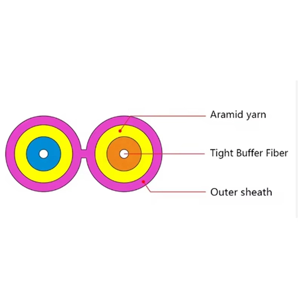
Gigabit is a decimal unit defined as per SI standard. 1 Gigabit = 1000 Megabits. The unit symbol for Gigabit is Gbit or Gb. Abbreviated as Gb, a gigabit is a method of measuring data transmission. When the "b" is uppercase, like GB, this refers to a gigabyte. What comes before a gigabit? What comes after a gigabit? Gigabit vs. other data measurements. What comes before a. Gigabit single-mode fiber optic module Common parameters of optical modules 1. Center wavelength 1) 850nm (MM, multi-mode, low cost, but short transmission distance, usually only 500M); 2) 1310nm (SM, single mode, large loss during transmission, small dispersion, generally used for transmission. In computer networking, Gigabit Ethernet (GbE or 1 GigE) is the transmission of Ethernet frames at a rate of a gigabit per second. The most popular variant, 1000BASE-T, is defined by the IEEE 802. It came into use in 1999 and has replaced Fast Ethernet in wired local networks due to. What is 1 Gig in Mbps? 1 Gigabit (Gb) is equal to 1000 Megabits (Mb). This conversion is important to understand because data transfer rates are commonly measured in Mbps, but many internet plans, network devices, and even transceivers are rated in Gbps. So. A gigabit (Gb) is a unit of digital information equal to 109 bits, or 1,000,000,000 bits. It uses the standard SI decimal prefix 'giga-'. It is important to distinguish.
[PDF]
In this Cisco Tech Talk, learn how to view the optical module status on a Cisco switch using the Command Line Interface (CLI). This video demonstrates how to access the optical module status, check for any issues, and monitor the health of your network's optical components. Learn. When optical modules operate on a switch, it is usually necessary to read the module's internal information to understand its working status—such as connection status and real-time metrics like optical power and temperature. Additionally, identifying module information helps detect coding. This chapter describes how to configure the Optical Amplifier Module and Protection Switching Module (PSM). When you plan to replace a configured optical module with a different type of optical module, you must clear the configurations of the old module before you install the new module. By checking module health, compatibility, and digital diagnostics, you can quickly confirm correct installation, detect optical problems, and maintain accurate hardware. Small Form-factor Pluggable modules (SFP module) are the workhorses of modern network connectivity, enabling flexible fiber optic or copper links between switches, routers, firewalls, and servers. Whether you're upgrading bandwidth, replacing a faulty unit, or reconfiguring your topology, knowing.
[PDF]
These modules are engineered with high-grade components designed to withstand the vibrations of washboard forest service roads and the temperature swings of high-altitude passes. 00 Original price was: $46. Activates High current relay when High Beams are turned on, used to add large light bars and driving lights without having to install additional switches in the dash. Plugs directly into Polaris Pulse System for switch lighting and keyed on ignition. The CanM8 Cannect Duo (Speed Pulse & High Beam) Interface is a 2-output CAN Bus interface which provides a quick solution for detecting high beam activity on vehicles which feature CAN Bus wiring. The Cannect Duo Interface also features a square pulsed speed signal output from the vehicle at a. Electronic technology has advanced so that an electronic control unit (ECU) is required to control the functions of full LED automotive headlights. An ECU consists of mainly LED drivers for headlight functions such as high beams, low beams, daytime running lights, position lights, turn indicators. This module resolves the issues with the headlight turning off, or flashing after the ignition is turned on. This issue is mainly affecting Chrysler, Jeep, Dodge vehicles, but some other modern cars will have this same issue. They offer a true plug-and-play experience, effectively eliminating the common flickering issues associated with.
[PDF]
A common test setup to evaluate Stressed Receiver Sensitivity involves measuring the Optical Modulation Amplitude (OMA) using a square wave, per the standard guidelines. Receiver sensitivity stands as a critical parameter impacting an optical transceiver's functionality. It denotes a module's capability to function in challenging environments and aids network operators in determining the system's maximum reach or link margin. These metrics provide insights into how well your transceivers perform under different conditions, ensuring seamless data transmission. Optical. Whether you're a network engineer validating new inventory or an integrator preparing for deployment, knowing how to test optical transceiver modules can save time, reduce failures, and ensure SLA compliance. Unchecked optical modules can cause: Testing ensures compliance with IEEE 802. 3 and MSA. In optical communication systems, sensitivity is a measure of how weak an input signal can get before the bit-error ratio (BER) exceeds some specified number. The standards body governing the application sets this specified BER. For example, SONET specifies that the BER must be 10 -10 or better. Why Fiber Optic Transceiver Testing is Important? Identify faults and failures: Transceiver testing helps in identifying any faults.
[PDF]
An optical module is a typically hot-pluggable optical transceiver used in high-bandwidth data communications applications. Optical modules typically have an electrical interface on the side that connects to the inside of the system and an optical interface on the side that connects to the outside world through a fiber optic cable. The form factor and electrical interface are often specified by an int. Electrical Interface TypesThere have been multiple variants of the electrical interface of optical modules that have been used over the years. The earliest forms of optical modules had an analog electrical interface. In the transmit dir. Many different forms of optical modulation and multiplexing have been employed in optical modules. The most common modulation technique historically has been or NRZ. Optical modules have a series of components inside, some of which have received attention from standards development organizations. In many cases, the baud rate of the optical interface do.
[PDF]
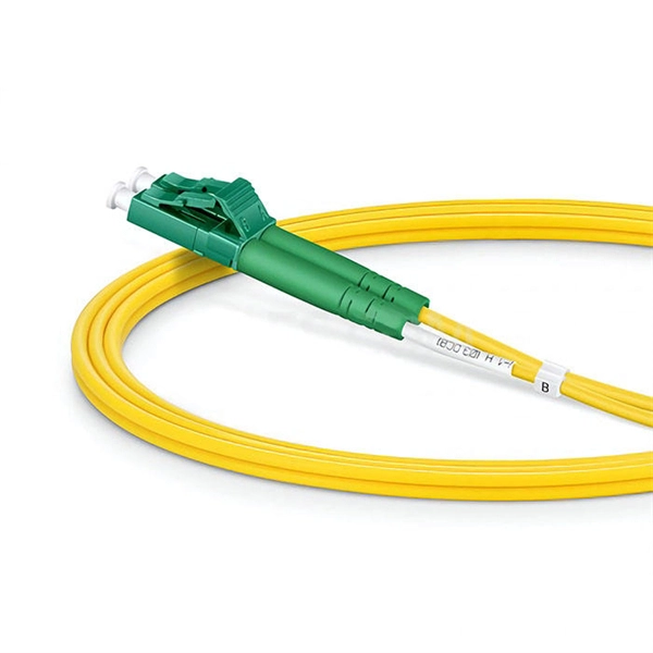
In the field of optical communication, the packaging of optical devices plays a crucial role in the performance and application of optical modules. Common optical device packaging methods include COB (chip-on-board packaging), BOX and coaxial packaging. Today, we will discuss the differences. This article analyzes the requirements of optical transceivers and discusses packaging methods and optical chip types to help readers better understand their design and manufacturing process. They are used in telecom and data communication applications and can be packaged in different ways, including TO, Box, and COB packaging. Regardless of the type of optical module, the. COB packaging means chip-on-board packaging, and the laser chip is adhered to the PCB substrate, which can achieve miniaturization, light weight, high reliability and low cost. The traditional single-channel 10Gb / s or 25Gb / s rate optical module uses SFP package to solder the electrical chip and. The optical transceiver module has three major components, which are opto-electronic devices (TOSA/ROSA), a circuit board with electronic components (PCBA) and optical interfaces (housings) such as LC, SC and MPO. Figure1: Components of an Optical Transceiver The optical transmitting part is.
[PDF]
Optical modules typically have an electrical interface on the side that connects to the inside of the system and an optical interface on the side that connects to the outside world through a fiber optic cable. An optical module is a typically hot-pluggable optical transceiver used in high-bandwidth data communications applications. Composition of Optical Modules The optical module, known as Optical Transceiver in. The optical module serves as a crucial component in optical fiber communication systems, operating at the physical layer, which is the lowest layer in the OSI model. Its primary function is to achieve optoelectronic conversion by converting electrical signals into optical signals and vice versa. Operating at the physical layer of the OSI model, optical modules are core devices in optical.
[PDF]
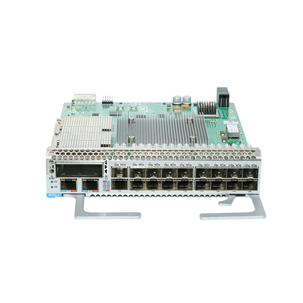
Huawei OLT Comparison: MA5600T vs MA5800 vs EA5800. This guide explains the architectural differences, PON technologies (GPON, XGS-PON), and helps you choose the right OLT for FTTx networks. MA5603T is multi service based while MA5683T is just OLT, MA5603T can support service like ADSL, VDSL, GPON etc, while MA5683T only supports GPON, P2P etc, but their hardware and configuration command is the same. MA5683T vs MA5680T? The only difference is capacity, MA5683T max support 6 service. Hi, This is ISP-Home. com, we excel in delivering high-performance fiber optical products, connecting you to a world of precision and reliability. As optical fiber access nodes keep moving closer to end users, OLTs are closer to end users. Deployment scenarios are complex and diversified. In this case, network needs OLTs with small volume and low density. The MA5801 series OLT is a compact and. When selecting a Huawei OLT (Optical Line Terminal), prioritize models that support your required number of subscribers, offer scalable GPON or XGS-PON technology, and integrate seamlessly with existing Huawei ONTs. For most mid-sized service providers, the MA5600T or MA5800-X17 provides the best. OLT Series: Access product manuals, HedEx documents, product images and visio stencils. The MA5800 is the industry's first smart aggregation OLT with a distributed architecture. It is positioned as the next-generation OLT for NG-PON.
[PDF]
First, inspect the optical module appearance for physical damage, cracks, missing components, poor solder joints, or burn marks. Next, compare voltage, resistance, and waveform parameters between a normal it and the suspected faulty one, both in powered and unpowered states. However, optical modules may become damaged or malfunction due to prolonged use or improper operation. In order to ensure the normal operation of the optical communication system, it is crucial to promptly inspect and repair damaged optical modules. This article will introduce some common methods. Optical modules in the application must have standardized operating methods, any irregular action may cause hidden damage or permanent failure. The primary causes of optical module failure are performance degradation due to ESD damage, and optical path discontinuity caused by optical. The optical module is faulty or not securely installed. The device management or driver software has a bug. Use an optical power meter to check whether the transmit optical power of the optical module is normal. However, during installation and daily operation, various issues may arise. Therefore, understanding common optical module.
[PDF]