High voltage relays are essential components in electrical systems. They control the flow of electricity in high voltage applications, enabling safe operations. These relays act as switches that open or close circuits. Their design ensures they handle high current levels without. Explore principles and configurations of protective relaying in high voltage systems. Ensure fast, selective fault clearance per IEC/IEEE standards. Protective relaying is the backbone of fault detection and system isolation in As transmission systems grow increasingly complex with integration of. A voltage protection relay system is a necessary component of any electrical setup. It prevents safety hazards and damage to equipment. It monitors voltage to determine if levels rise too high or dip too low. Many industries use voltage protection relay systems, especially those in high-voltage. Eaton's protective relays provide you with unique microprocessor-based devices that eliminate unnecessary trips, mitigate arc faults, protect motors and breakers, and provide system information to help you better manage your system. Our predictive diagnostic solutions include non-destructive testing. In electrical engineering, a protective relay is a relay device designed to trip a circuit breaker when a fault is detected. They are intended to quickly identify a fault and isolate it so the balance of the system continue to run under normal conditions.
[PDF]
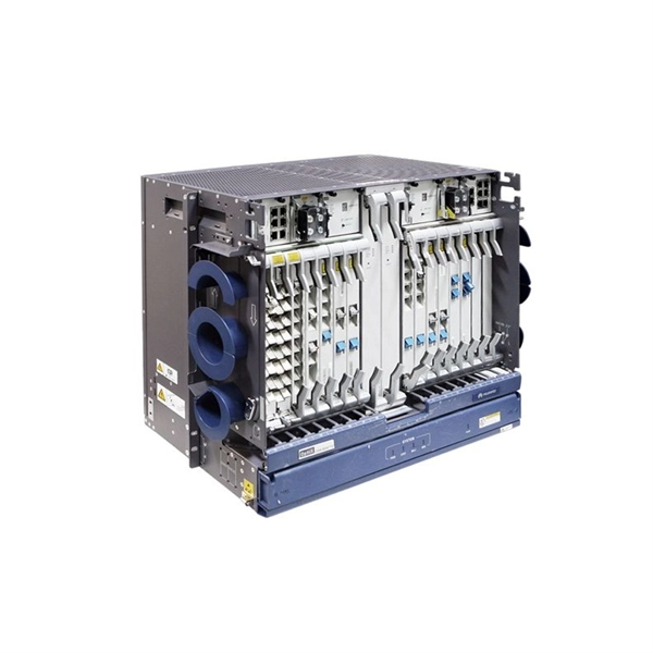
Definition of Protective Relay A protective relay is an automatic device that detects abnormalities in an electrical circuit and closes its contacts. This action completes the circuit breaker's trip coil circuit, causing the breaker to trip and disconnect the faulty section from the. Eaton's protective relays provide you with unique microprocessor-based devices that eliminate unnecessary trips, mitigate arc faults, protect motors and breakers, and provide system information to help you better manage your system. Our predictive diagnostic solutions include non-destructive testing. Here, Several circuit breakers in the fault current paths from the generators to the fault location have been tripped. Note that all generators- the power sources – have been disconnected. Therefore, the whole system has gone down, even though many circuit breakers have remained closed. The relay continuously monitors electrical parameters such as current, voltage, frequency, and phase angle. When these parameters deviate from normal operating conditions or. The rectangular devices are test connection blocks, used for testing and isolation of instrument transformer circuits. : 4 The first protective relays were electromagnetic. Protective Relays - Technical Seminar Nov 2016 - Copyright: IEEE 2 Abstract: Protective relays and devices have been developed over 100 years ago to provide “lastline”of defense for the electrical systems.
[PDF]

This document provides a comprehensive technical overview of the Ring Main Unit (RMU), serving as a reference for power system design, selection, and maintenance. Ring Main Units (RMU s) and Medium Voltage (MV) Switchgear are crucial in MV power distribution. Globally, they each hold about half the market share. MV switchgear handles primary distribution for large industrial facilities and grid infrastructure. RMUs, however, shine in secondary distribution. RMUs are commonly used in secondary distribution systems, particularly in urban areas, industrial complexes, and commercial. Scope of Application: The Ring Main Unit (RMU) is a compact switchgear device used in medium-voltage power distribution systems (typically 10kV–35kV). Some of the key features of the RMU includes SF6 gas insulation, compact and modular construction, integral protection system, fully extendable options. SFA-RM units are designed for supplying reliable energy, protecting electrical equipment in secondary distribution networks up to 17. Their compact design makes them suitable for various network applications such. Loading. Company Introduction:The New Concept Electric Inc. (NCE) was founded in October 2001, with a registered capital of 57 million Yuan. The company now covers an area of 77, 601 square meters (116 acres), and has a building area of 80, 451 square meters.
[PDF]
The third part represents the number of spots in the beam splitter. The naming principle of the beam splitter is easy to illustrate with the following example. The models listed in the following table are examples After years of exploration, we can maintain all process parameters of the beam splitter stable and. A beam splitter or beamsplitter is an optical device that splits a beam of light into a transmitted and a reflected beam. It is a crucial part of many optical experimental and measurement systems, such as interferometers, also finding widespread application in fibre optic telecommunications. a laser beam) into two (or sometimes more) beams, which may or may not have the same optical power (radiant flux). Newport offers a wide variety of Beamsplitters in various shapes. Circular beamsplitters, plate beamsplitters and cube beamsplitters can be purchased for polarizing or non polarizing beamsplitting. Thorlabs offers a wide range of optical beamsplitters. Our plate beamsplitters have a coated front surface that determines the beam splitting ratio while the back surface is wedged and AR coated in order to minimize ghosting and interference effects. Additionally, beamsplitters can be used in reverse to combine two different beams into a single one. Beamsplitters are often classified according to their construction: cube or plate.
[PDF]
Use this fiber Bragg gratings buying guide to compare major types, define selection criteria, and find suppliers: Professional purchasing of high-value photonics products is a substantial responsibility, where a structured decision-making process is essential. RP Photonics offers a lot of help: Get. Single-mode Fiber Bragg Grating Sensors come in various types, suitable for distinct applications. These include: A temperature sensor integrated into an optical fiber uses a Fiber Bragg Grating (FBG) to measure temperature variations. You can easily wholesale quality fiber bragg grating sensor at wholesale prices on Made-in-China. The pricing structure varies considerably between bare fiber FBG sensors and packaged configurations. Bare fiber temperature sensors offer the most economical option. 6Wresearch actively monitors the Vanuatu Fiber Bragg Grating Market and publishes its comprehensive annual report, highlighting emerging trends, growth drivers, revenue analysis, and forecast outlook. Our insights help businesses to make data-backed strategic decisions with ongoing market dynamics. 0µm wavelength range. The FBG Filter Embedded Connector is designed for fiber-to-the-home applications.
[PDF]
Single-mode fiber optic cable typically has a single core. This means that it consists of a single strand of glass fiber that carries light signals. The core is the central part of the cable through which the light travels, surrounded by a cladding layer that helps guide the light. One key factor is the number of cores, which impacts how much data you can transmit. This post will guide you through understanding fiber optic cores and selecting the perfect cable for your needs. Single-mode: A. The number of optical cores in an optical fiber is the total number of equipment interfaces multiplied by 2, plus 10% to 20% of the spare quantity, and if the communication mode of the equipment has serial communication and equipment multiplexing, you can reduce the number of cores. The number of. Common fiber cores include 1 core, 2 cores, 6 cores, 8 cores, etc., and there are many types. The total number of cores for a 1pc fiber patch cable is calculated as the number of. The most common type of fiber optic cable used in telecommunications is single-mode fiber, which usually has a single core.
[PDF]
The arc extinguishing mode of neutral grounding via arc suppression coil (ASC) is widely used in the distribution network. With the increasing application of active intervention type arc extinguishing device (AIT-A.
[PDF]
A firewall is a network security device that separates a trusted internal network from an external network deemed untrustworthy, such as the internet. It regulates incoming and outgoing network traffic based on preset security rules. Here's how firewalls work, their advantages, main types and common applications. Summary: A firewall is a security device that uses a set of rules to monitor and filter network. A Firewall is a network security system, available as hardware or software, that monitors and controls incoming and outgoing traffic based on predefined rules. It acts like a security guard, filtering data packets to either: Accept: Allow the traffic. Reject: Block with an error response. Drop:. Firewalls act as a gatekeeper for network communications examining and filtering network traffic to ensure only authorized and safe traffic passes through. This process protects the network from unauthorized attempts to gain access, cyber attacks, and malicious code. It functions by.
[PDF]
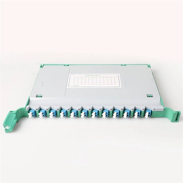
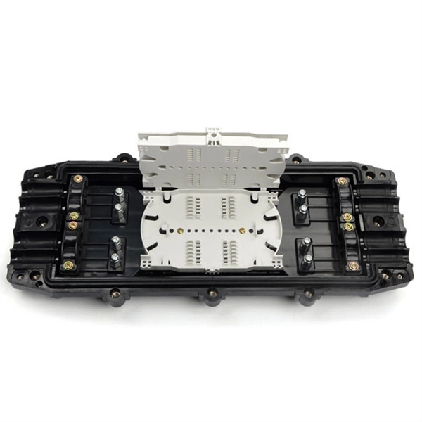
You simply multiply the number of splices by the estimated loss per splice. It's that easy! ✨ Let's say you have a long fiber run that requires 4 fusion splices to connect different cable segments. 4 dB is the total attenuation you'll add to your loss budget just for the. Fusion splicing is the process of fusing or welding two fibers together usually by an electric arc. Fusion splicing is the most widely used method of splicing as it provides for the lowest loss and least reflectance, as well as providing the strongest and most reliable joint between two fibers. There are several ways to know the number of multi-spliced cores. For example, 12 core fibers, 12*2=24 cores, 12 cores at the beginning and 12 cores at the end; 2. Count the number of optical fiber. Calculating the total loss from splices in a cable run is wonderfully straightforward. Connectors: Total number of connectors in design. Laser: A device which produces a single frequency light. The guide provides the complete workflow, covering safety precautions, tool selection, fiber preparation, fusion operation, quality control, and. Recommendation ITU-T L. 12 specifies splices of single-mode and multimode optical fibres. It describes suitable procedures for splicing that should be carefully followed in order to obtain reliable splices between single optical fibres or ribbons.
[PDF]
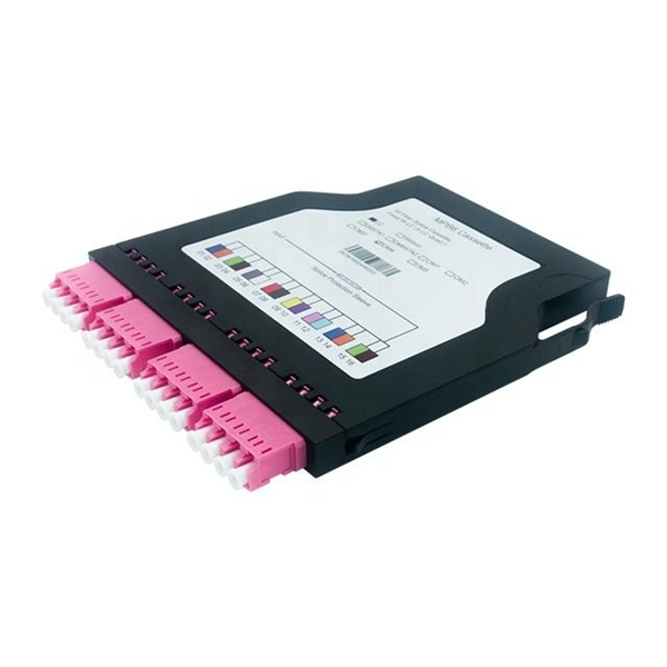
The number of optical cores in an optical fiber is the total number of equipment interfaces multiplied by 2, plus 10% to 20% of the spare quantity, and if the communication mode of the equipment has serial communication and equipment multiplexing, you can reduce the number of cores. The number of. There are several ways to know the number of multi-spliced cores. For example, 12 core fibers, 12*2=24 cores, 12 cores at the beginning and 12 cores at the end; 2. If. This article will walk you through the basics of fiber optic cores and provide practical guidance for selecting the suitable fiber optic cable to meet your networking needs. Fiber cores are the heart of fiber optic cables, transmitting light signals that carry data. Made from either high-quality. By adopting the TIA/EIA‑598C standard, you gain a universal “language” of colors that speeds identification, reduces miswiring, and enhances safety across cable jackets, connectors, buffer tubes, and splice trays. Error Reduction: A standardized palette prevents costly mis‑splices and. The number of cores is the number of glass fibers contained in each fiber. First of all, clearly know the number of wiring points in this layer, calculate the number of switches, and whether the connections.
[PDF]
Enter the dimensions of the cable tray, the desired fill ratio, and the diameter of the cables to calculate the cable tray capacity. This calculator helps determine the maximum number of cables that can be laid in a cable tray while adhering to the specified fill ratio. The following formula is. Calculate cable tray sizing and fill capacity based on tray dimensions, cable diameter, number of cables, and maximum fill percentage per electrical code. Determine whether cables fit within safe fill limits. Cable tray fill capacity is governed by electrical codes (typically NEC Article 392) which. Our cable tray fill calculator is designers to compute the appropriate size and capacity of cable trays. 5 inches, in a 4-inch deep cable tray. The calculator would help determine if the chosen tray is sufficient or if a larger size is. A Cable Tray Capacity Calculator is an essential tool for electrical engineers, contractors, and project managers involved in the installation and management of electrical cables. NEC code limits tray fill to 40– 50% depending on tray type, leaving room for airflow, future cables, and bend radius. Calculate the total cable cross-section area and divide by tray area. Follow these simple steps: Define Tray Dimensions: Enter the width and depth of your planned cable tray (in mm or inches). Select Fill Standard: Choose 40% for power cables (NEC compliant) or 50% for.
[PDF]
This study aims to develop a simple yet efficient performance-based design optimization methodology for cable tray systems in building structures. In the paper, the drift ratio between adjacent supports i.
[PDF]
Professional home circuit calculator per NEC Article 210 and 220. Determines the total number of branch circuits, wire sizes, breaker ratings, and GFCI/AFCI protection requirements for residential electrical systems. Covers general-purpose lighting circuits, small appliance circuits, laundry. Before determining the required number of circuits and associated calculations, let's define and differentiate between branch circuits, general-purpose lighting branch circuits, and individual branch circuits. According to NEC Article 100 – Definitions: Branch Circuit: Refers to the conductors. Before we dive into calculations, let's get familiar with a few essentials: 1. Your Project's Total Power Demand This isn't just adding up wattages randomly. Think of your home as a busy kitchen—not every appliance runs at once. Do you really need the hair dryer, microwave, and vacuum running. Professional electrical panel schedule tool for creating detailed load distributions, calculating circuit loads, balancing phases, and ensuring NEC compliance for electrical distribution panels. Panel schedules are essential for electrical system documentation, load analysis, and NEC compliance. Compute the branch circuits, feeders, service-entrance conductors, and wire protection. How do you determine the minimum number of general lighting and general-use branch circuits required by the NEC for dwellings? A.
[PDF]
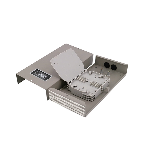
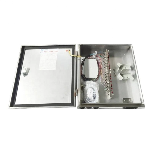
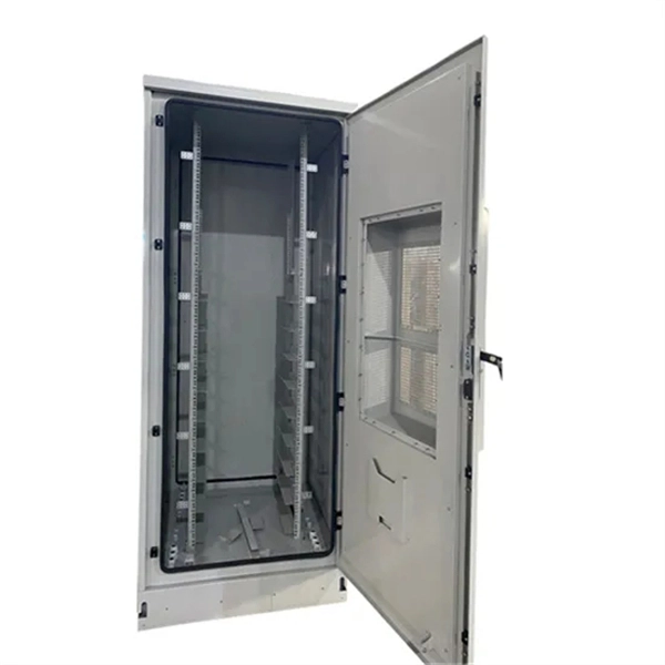
A fiber to Ethernet converter, often called a media converter, is a networking device that converts light signals from fiber optic cables into electrical signals used by Ethernet cables. This allows you to connect devices that use different types of cabling, such as a computer. An ONT, or Optical Network Terminal, is a device that converts fiber optic signals from your Internet provider into Ethernet signals that your devices can use. It's a key part of any Fiber to the Home (FTTH) setup. If your home uses cable Internet instead of fiber, you don't need an ONT. You'll use. For networking scenarios where the standard 100-meter reach of copper Ethernet cables (UTP or STP) is insufficient, Ethernet media converters for extended distance connectivity present a professional solution to extend connectivity. Connection Relationship: Step 1: Access outdoor fiber optic cables into fiber terminal box for the purpose of splicing the optical fiber cable and fiber optic.
[PDF]
The Central Box 220 is a switchboard designed for the complete management of servos in a model with an emphasis on safety. The Central Box 220 has a unique design that provides overload protection for up to 11 Standard (up to 415 oz/in, 30 kg/cm) and 4 Ultra Torque (up to 830. Input / output power is communicated directly, so the input voltage equal to the steering gear and receiver power supply voltage, simply use the different voltage values of the battery can be adapted to a variety of high and low voltage actuator and receiver. PowerBox-Systems Americas - We develop and produce modern, innovative and reliable power supply systems for the modeler. We offer RC accessories from fuel tubes to Engines. From Small servo arm to large landing gears. We help RC hobbies build Fixed wing airplane quickly and easily. Find Spinners, propellers, wing bags, Fuel Tanks, Retracts, Starters in our Hobby shop. Both power and servo signal are amplified - Can drive up to 10 meters servo wire per channel ! "Flight Deck" for mounting receiver at top of board. Can be removed (permanent) if desired 12 Inputs 24 Buffered/Filtered and amplified outputs Both power and servo signal are amplified - Can drive up to.
[PDF]