Use this Protection Relay Setting Calculator to calculate pickup current, time multiplier settings (TMS), operating time, coordination time interval (CTI), and plug setting multiplier (PSM) using fault current, CT ratio, and IEC 60255 curve parameters. of protective relays in terms of protecting high voltage lines. At the beginn ng of the article it is drawn up process to protect power lines. Consequently, it is shown the method of calculation for a particular power line a d performed the calculation for setting the distance protection. These calculations are critical in industrial. ve reliable and properly coordinated relay settings. Protection coordination refers to the systematic arrangement and interaction of protective devices within an electrical distribution network to ensure that faults are isolated in a controlled and orderly manner. The. With the help of these spreadsheets below, you can make your endless calculations much easier! Contact us for more information and download:.
[PDF]
Protection: CVTs supply voltage signals to protective relays, enabling them to detect faults and initiate appropriate actions, such as circuit breaker tripping. Control: CVTs can also be used in control systems to monitor voltage levels and provide feedback for voltage regulation. Capacitive Voltage Transformers (CVTs) are common in high-vo tage transmission line applications. These same applications require fast, yet secure protection. However, as the requirement for faster protective relays grows T models whose purpose is to identify which major CVT components contribute. ve Voltage (CVT) and Capacitance Coupled Voltage Transformers (CCVT). With this comprehensive range of accurate power sensing devices coupled with GE's vertical integration approach and skilled design engineering staf, we work closely with our globa ems for applications ranging from high-voltage to. Capacitive Voltage Transformers (CVTs), also known as capacitor voltage transformers, are essential components in high-voltage power systems. They provide a cost-effective and reliable means of measuring voltage and supplying power to protective relays and metering equipment. This essay will delve. Potential transformers and coupling capacitor voltage transformers (CCVT's) have been used successfully for providing voltage to the inputs of meters and relays since the 1960's. It utilizes a capacitive voltage divider in conjunction with an electromagnetic voltage converter to provide a.
[PDF]
of relay protection coordination for a PV power plant connected to the distribution network is presented. In recent years, installation of PV power plants in the distribution network has increased significantly. I.
[PDF]
The document discusses the principles and philosophy of protective relaying in power systems, emphasizing its role in preventing equipment damage and improving system reliability. Following a review of power system equipment, students define common protection terms and use common IEEE device designations while performing acceptance tests on protective relay schemes and elements. Combined with logic statements and a breaker control scheme, students develop a coordinated. IEEE/IAS/I&CPSD Protection & Coordination WG Chair Jacobs Canada, Calgary, AB rasheek. com IEEE Southern Alberta Section PES/IAS Joint Chapter Technical Seminar - November 2016 Protective Relays - Technical Seminar Nov 2016 - Copyright: IEEE 2 Abstract: Protective relays and devices. Georgian DS is a station that is supplied from a 44 kV feeder with one 10. 0 MVA delta/wye transformer with Z=6. The rated voltage of the primary winding is 46. The Question: ELEC 3007 - Assignment 7 - Protection Co-ordination Study (50) Name: This assignment will involve the relay. The Multilin™ 8 Series platform of advanced protection and control relays delivers high quality and performance management, protection and control for transformer, generator, motor and feeder applications. It outlines the factors influencing protection schemes, the importance of designing systems for selectivity and speed.
[PDF]
The relay block comprises the two protection units, phase protection unit and earth protection unit. When the value of the current in any of the phases is greater than the pick up value, the phase protecti.
[PDF]

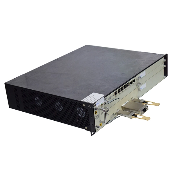
This document provides a comprehensive technical overview of the Ring Main Unit (RMU), serving as a reference for power system design, selection, and maintenance. Ring Main Units (RMU s) and Medium Voltage (MV) Switchgear are crucial in MV power distribution. Globally, they each hold about half the market share. MV switchgear handles primary distribution for large industrial facilities and grid infrastructure. RMUs, however, shine in secondary distribution. RMUs are commonly used in secondary distribution systems, particularly in urban areas, industrial complexes, and commercial. Scope of Application: The Ring Main Unit (RMU) is a compact switchgear device used in medium-voltage power distribution systems (typically 10kV–35kV). Some of the key features of the RMU includes SF6 gas insulation, compact and modular construction, integral protection system, fully extendable options. SFA-RM units are designed for supplying reliable energy, protecting electrical equipment in secondary distribution networks up to 17. Their compact design makes them suitable for various network applications such. Loading. Company Introduction:The New Concept Electric Inc. (NCE) was founded in October 2001, with a registered capital of 57 million Yuan. The company now covers an area of 77, 601 square meters (116 acres), and has a building area of 80, 451 square meters.
[PDF]

Find and discover Relay buyers & importers for all products in Benin, featuring details on their shipment activities, trade volumes, trading partners, and more. View all relay suppliers based on products in Benin. How does 6Wresearch market report help businesses in making strategic decisions? 6Wresearch actively monitors the Benin Protective Relays Market and publishes its comprehensive annual report, highlighting emerging trends, growth drivers, revenue analysis, and forecast outlook. Our insights help. There are 72 Manufacturers in Benin as of April 1, 2026; which is an 9. 09% increase from 2023. The top three states with the most Manufacturers are Atlantique Department with 20 Manufacturers, Borgou Department with 14 Manufacturers, Littoral Department with 11 Manufacturers. Subscribe to global trade data intelligence to discover new business opportunities. Top 10 Companies in Benin: A Profile of Industry Leaders Benin, a coastal nation in West Africa, has witnessed significant economic growth in recent years. The country's business landscape is dominated by a diverse range of companies, spanning various industries and contributing to its overall. It is bordered by Togo to the west, Nigeria to the east, and Burkina Faso and Niger to the north. A majority of the population live on its small southern coastline on the Bight of Benin, part of the Gulf of Guinea in the northernmost tropical portion of the Atlantic Ocean. This report offers comprehensive.
[PDF]
Thermal overload relays are widely used to protect motors. These devices work on the thermal effect principle. A thermal relay is an electromechanical device that detects temperature changes in electrical circuits, protecting equipment from overload and overheating. Thermal relays are critical components in electrical systems, designed to protect motors and other electrical equipment from damage caused by. Thermal Relay Definition: A thermal relay is defined as a device that uses the unequal expansion rates of metals in a bimetallic strip to detect overcurrent conditions. Working Principle: The thermal relay operates by heating a bimetallic strip, causing it to bend and close normally open contacts. So, the thermal relay is one of the types of the relay, used to provide complete safety against single phasing, unbalanced voltages & overloads. Thermal relays are the perfect solution for providing protection to motors which provides the most precise tripping for the electric motor during single. Introduction — The Core Device Protecting Industrial Motors Thermal overload relays are one of the most essential protection components in industrial motor circuits. Correct understanding and configuration ensure equipment safety and longevity. Its performance matches the actual heating characteristics of.
[PDF]

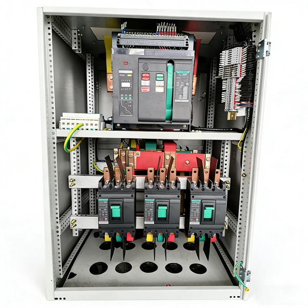
A protection relay tripping circuit connects relays to breakers for fast fault isolation. Key components include trip/close coils and anti-pumping relays. Proper design, testing, and maintenance ensure reliable overcurrent, differential, and auto-reclosing protection in power. The protection relay tripping circuit refers to the critical electrical control loop that executes trip/close commands from protective relays to circuit breakers, ensuring rapid fault isolation in power systems. Essential. Electromechanical protective relays at a hydroelectric generating plant. The relays are in round glass cases. In electrical engineering, a protective relay is a relay device. A protective relay is an intelligent electrical device designed to detect faults in power systems and initiate corrective actions such as tripping a circuit breaker. Its main purpose is to safeguard electrical equipment like transformers, generators, and transmission lines from damage due to. By definition, a protective relay is a switchgear device that detects faults and initiates the circuit breaker operation to isolate the problematic component of the system. Electrical values are measured by these relays to determine abnormal circumferences of a circuit. It functions as a watchdog by constantly surveying multiple system components including voltage, current, frequency, and phase angle.
[PDF]

The standard industry practice is to set overload relays at 125% of the motor's nameplate Full Load Ampere (FLA) rating. Plug Setting Multiplier (PSM) indicates how many times the determined relay secondary current (typically the CT secondary) exceeds the relay pickup (plug) current. It is the key quantity utilized in IDMT (inverse definite minimum time) curves to calculate the basic operating time. PSM (Plug Setting. An overload relay is a crucial device for motor control, designed to prevent motors from overheating or suffering winding damage due to excessive current. Motor overload relays protect against sustained overcurrent conditions that cause dangerous overheating, insulation breakdown, and premature. Overload relays protect motors and equipment from thermal damage caused by prolonged overcurrent conditions. IEC 60255 defines standards, formulas, and performance requirements, enabling accurate calculations and real-world applications. How is the overload relay current calculated? Why include. Setting motor overload relays correctly is critical for protecting AC induction motors from sustained overcurrent conditions while avoiding nuisance trips during normal starting transients. This occurred when the relay F was set at 1. The complaint was that the relay tripped instantly on overload when the thermal damage curve show plotted for a specific current that was less t an.
[PDF]

An analog accessory for use in a system for testing protection relays is provided, comprising inputs connectable to the current outputs of a test-set for protection relays and voltage outputs connectable to a protection relay to be tested. The register contains national patents and information related to European Patents validated in Malta. It currently provides European patent numbers, filing dates, titles, abstracts, classifications, applicants, bibliographic data, status, priorities, expirations, annuity/renewal fees. The utility model discloses a power plant relay protection tester, belonging to the technical field of relay protection testers, which comprises a relay protection tester body and a shell for placing the relay protection tester body, wherein a partition plate is arranged in the shell, a driving. Application to amend a patent application or registration. Convert a European patent application to a National patent. Request an extension of a time limit for the submission of patent documents. By providing an electric circuit adapted to convert current. Background Relays and metering are an important part of power generation, power transmission, and power con- sumption in electric power systems and the power grid. Relays provide monitoring and protection of equipment and personnel.
[PDF]
This study aims to develop a simple yet efficient performance-based design optimization methodology for cable tray systems in building structures. In the paper, the drift ratio between adjacent supports i.
[PDF]
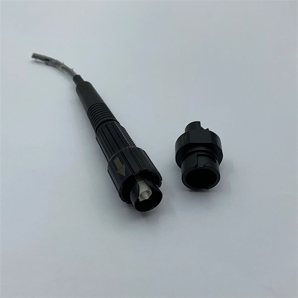
To set up your router for fiber internet quickly, connect the router to your fiber modem, access the router's settings via a web browser, and input the provided ISP credentials. Make sure to update the firmware, configure Wi-Fi security, and customize your network name for optimal performance. With. However, setting up a fiber optic connection to your router can seem daunting if you're unfamiliar with the process. In this guide, we'll walk you through how to connect a fiber optic cable to a router safely and efficiently. Why Use Fiber Optic Internet? Before diving into the setup, let's quickly. Fiber internet installation delivers the high-speed connectivity modern businesses need for video conferencing, cloud applications, and data-intensive operations. We've done the research for you and put together this in-depth guide that lists multiple options, their details, reviews, and pros and cons. This should help you make an informed decision. Yes, you can often use your existing router with fiber optic internet, but there are crucial considerations. Understanding compatibility, potential limitations, and when an upgrade is necessary will ensure you get the most out of your high-speed connection. This guide will break down everything you. Setting up a fiber internet connection requires understanding key hardware components and following a specific connection sequence to establish your home network.
[PDF]

The C-Channel & Steel Channel Calculator is a free engineering tool that instantly computes weight, bending moment, shear force, and deflection for standard or custom C-channels. We independently provide precision steel tools, calculators, and expert resources for steel, metalworking, construction, and industrial projects. Interactive calculator for American standard steel C channels. Select the channel depth and weight per unit length to obtain dimensions, cross-section area, moments of inertia, section modulus and radii of gyration according to ASTM A6/A6M. Use this steel C channel sizes calculator to quickly look. SkyCiv C Channel Load Capacity Calculator is a free tool designed to help you determine the strength and capacity of steel channel beams. It calculates the capacity of a channel and angle section based on the dimensions, span length. This tool calculates the properties of a U section (also called channel section or U-beam). Enter the shape dimensions h, b, t f and t w below. The calculated results will have the same units as your input. For full table with Static parameters Moment of Inertia and Elastic Section Modulus - rotate the screen! The standard method for specifying the dimensions of a American Standard Steel Channels is like C 5 x 9.
[PDF]

Calculate horizontal, vertical, or compound cable tray offsets based on bend angle, offset distance, and available installation space. Use this tool to estimate sloped section length, horizontal run requirement, cut marks, and installation feasibility. Measure this distance along the straight tray. Determine the total usable cross-sectional area of the cable tray by multiplying its width by its height (or depth). Calculate Cable Cable Calculate the cross-sectional area of a single cable, then multiply by the total number of cables. For mixed cables, sum the areas of all individual cables. The right cable tray sizing calculator helps engineers turn cable schedules into a verified tray width and fill check before material ordering and site installation. IEC 61537 covers cable tray and cable ladder systems for the support and accommodation of cables, while NEC Article 392 governs cable. Calculate cable tray fill ratio, weight loading, and derating factors for multi-standard compliance. This calculator features an interactive interface with advanced visualizations. Open the full calculator for the best experience. This calculator determines if your tray meets industry standards (typically 30-50% fill for alternating single-layer or 40-50% for random arrangement). Follow these simple steps: Define Tray Dimensions: Enter the width and depth of your planned cable tray (in mm or inches).
[PDF]


