It works on the principle of sensing residual current which is why it is called a residual current device. Nowadays, all domestic and commercial electrical systems and circuits use RCDs. Today, we will see how you can connect an RCD to the distribution . Hey, in this article we are going to see the RCD Wiring diagram and its connection procedure. RCD means Residual Current Device. It is an electrical protective device that protects electrical circuits and devices from some electrical faults such as leakage faults, electrical shock, current. Distribution board is a safe system designed for house or building that included protective devices, isolator switches, circuit breaker and fuses to connect safely the cables and wires to the sub circuits and final sub circuits including their associated Live (Phase) Neutral and Earth conductors. Residual-current devices, commonly referred to as RCDs, are used in many practical applications. They can be found in fuse boxes, electrical switchgears or industrial machine control systems. Therefore. A distribution box uses MCBs, RCDs, and busbars to protect circuits, prevent shocks, and ensure safe power distribution in homes and buildings. This box keeps your home or building safe from electrical dangers. Devices that operate with electricity can cause leakage due to various reasons. If this leakage is not detected and cut off in time, it can lead to.
[PDF]
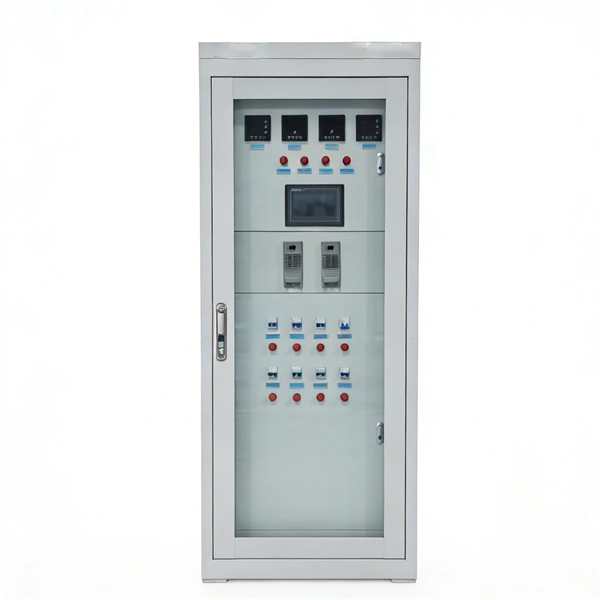
High voltage relays are essential components in electrical systems. They control the flow of electricity in high voltage applications, enabling safe operations. These relays act as switches that open or close circuits. Their design ensures they handle high current levels without. Explore principles and configurations of protective relaying in high voltage systems. Ensure fast, selective fault clearance per IEC/IEEE standards. Protective relaying is the backbone of fault detection and system isolation in As transmission systems grow increasingly complex with integration of. A voltage protection relay system is a necessary component of any electrical setup. It prevents safety hazards and damage to equipment. It monitors voltage to determine if levels rise too high or dip too low. Many industries use voltage protection relay systems, especially those in high-voltage. Eaton's protective relays provide you with unique microprocessor-based devices that eliminate unnecessary trips, mitigate arc faults, protect motors and breakers, and provide system information to help you better manage your system. Our predictive diagnostic solutions include non-destructive testing. In electrical engineering, a protective relay is a relay device designed to trip a circuit breaker when a fault is detected. They are intended to quickly identify a fault and isolate it so the balance of the system continue to run under normal conditions.
[PDF]
Distance relays, also known as impedance relay, differ in principle from other forms of protection in that their performance is not governed by the magnitude of the current or voltage in the protected circuit but rather on the ratio of these two quantities.OverviewIn, a protective relay is a device designed to trip a when a is detected. The first protective relays were electromagnetic devices, relying on coils operating on moving par. Electromechanical protective relays operate by either, or. Unlike switching type electromechanical with fixed and usually ill-defined operating voltage thresholds. Electromechanical relays can be classified into several different types as follows: "Armature"-type relays have a pivoted lever supported on a hinge or knife-edge pivot, which carries a moving contact. These relays may.
[PDF]
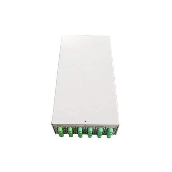
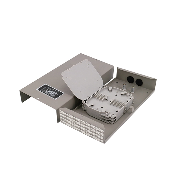
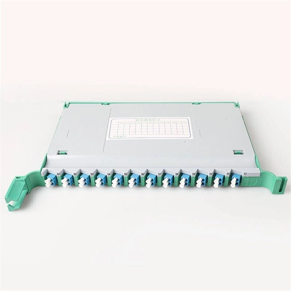
EPON means Ethernet Passive Optical Network. It uses fiber-optic cables. These cables give fast and steady internet to homes and businesses. EPON modules play a pivotal role in facilitating fast and reliable data transmission over fiber optic networks, offering enhanced bandwidth capabilities and improved network efficiency. In this step-by-step introduction to EPON modules, we will delve into the basic concepts, various types, benefits. In today's connected world, EPON (Ethernet Passive Optical Network) is a game-changer for delivering blazing-fast internet. This guide dives deep into EPON technology, its benefits over alternatives like GPON, and the critical role of optical modules. Whether you're a network engineer or a tech. A passive optical network (PON) is a fiber-optic telecommunications network that uses only unpowered devices to carry signals, as opposed to electronic equipment. In practice, PONs are typically used for the last mile between Internet service providers (ISP) and their customers. In this use, a PON. At the heart of this evolution are Passive Optical Networks (PON)-built around OLT + ONU/ONT + ODN (splitters)-which enable point-to-multipoint fiber access with excellent cost per user and energy efficiency. It uses only optical fibers to transmit data, voice, and video services. EPON is based on the Ethernet standard and is therefore compatible with most existing.
[PDF]

Mouser offers inventory, pricing, & datasheets for Fiber Optic Sensors. Pricing (USD) Filter the results in the table by unit price based on your quantity. A tariff of 8% may be applied if shipping to the United States. The Optilab FOCS-1550-PG is designed for fiber optic current sensing. This device is composed of a polarizer, a Y-junction coupler and dual electro optic phase modulators. Based on Lithium Niobate (LiNbO3), FOCS-1550-PG is fabricated with Annealed Proton Exchange (APE) optical waveguides. The. The FOCS Series Fiber Optical Current Sensors are passive, all-dielectric devices designed for precise current measurement without metal components, making them immune to electromagnetic interference noise. They measure current using light that passes through a Faraday fiber and reflects back from. A fiber optic current sensor operates based on the Faraday effect, a magneto-optic phenomenon where the polarization plane of light rotates in proportion to the magnetic field generated by an electric current. These sensors are inherently immune to electromagnetic interference (EMI), making them. The global Fiber Optic Current Sensors (FOCS) market was valued at US$ 239. 6 million in 2023 and is projected to reach US$ 401. 5% during the forecast period.
[PDF]
This video shows real on-site footage of electrical installation, demonstrating safe and standardized wiring methods used by professionals. more Learn how to wire a distribution box step by step!. A distribution box, also known as a distribution board, electrical panel, or breaker box, is an enclosure that houses electrical components responsible for distributing electricity throughout a building. more Learn how to wire a distribution box step by step! This video shows real on-site footage of. In this video, we'll walk you through the process of wiring a home distribution box with a detailed connection diagram. Whether you're an electrician or a DIY enthusiast, this guide will help you understand the basics of home electrical distribution. What is Distribution Board? Distribution board. Connection method: Each switch takes a wire from the incoming point and connects it to the incoming end of the switch, or uses parallel connection to reduce the difficulty of wiring. Wiring Direction: Wiring between the main circuit breaker and each branch circuit breaker in the box generally. Understanding the wiring diagram of an electrical panel box is essential for electricians and homeowners alike, as it allows them to troubleshoot any electrical issues, carry out repairs, or make additions to the system. It takes the incoming power and safely distributes it to different circuits throughout your building. However, the key to.
[PDF]
The arc extinguishing mode of neutral grounding via arc suppression coil (ASC) is widely used in the distribution network. With the increasing application of active intervention type arc extinguishing device (AIT-A.
[PDF]
An optical module is a typically hot-pluggable optical transceiver used in high-bandwidth data communications applications. Optical modules typically have an electrical interface on the side that connects to the inside of the system and an optical interface on the side that connects to the outside world through a fiber optic cable. The form factor and electrical interface are often specified by an int. Electrical Interface TypesThere have been multiple variants of the electrical interface of optical modules that have been used over the years. The earliest forms of optical modules had an analog electrical interface. In the transmit dir. Many different forms of optical modulation and multiplexing have been employed in optical modules. The most common modulation technique historically has been or NRZ. Optical modules have a series of components inside, some of which have received attention from standards development organizations. In many cases, the baud rate of the optical interface do.
[PDF]