Fiber optic cables can be run anywhere from 2 kilometers to over 100 kilometers without signal regeneration, depending on the cable type and application. Fiber optic cable transmission distance is determined by two primary physical factors that affect signal quality as light travels through the fiber medium. The greater the distance, the greater. In this blog, I will discuss the fiber optic cable distance, the effect factors, how to choose the right fiber optic cables, and how to compare the transmission distances of single-mode and multimode fiber optic cables. Single-mode fiber (SMF) supports distances up to 40-100+ kilometers for standard applications, while multimode fiber (MMF) is typically limited. Fiber optic cables are the backbone of modern communications, enabling high-speed data transfer over vast distances. Unlike traditional copper cables, fiber optic cables use light to transmit data, resulting in faster speeds and greater bandwidth capabilities. Chromatic dispersion This is a key factor affecting single mode fiber distance. While this technology offers higher speeds and longer distances than traditional copper wiring, physical limitations impose distance constraints. Light pulses degrade as they travel over long spans, primarily.
[PDF]
Need some clarification about NEC 770. 47 (B), it says that the direct buried conductive fiber optic cable shall be 12 in (300 mm) away from the power cables. Separating high-voltage power cables from low-voltage communication cables is a fundamental requirement in any electrical installation. This practice is mandatory for two distinct reasons: ensuring the safety of the structure and its occupants, and preserving the integrity of sensitive data. Maintaining proper separation between power, data, and limited energy cabling is foundational to system performance, safety, and code compliance. Separation isn't just an EMI precaution — it protects signaling, reduces rework, and ensures pathways meet inspection expectations across risers. TECHNICAL GUIDELINE July 30, 2020 TG030 Rev. 4 Pathway Separation Between Telecommunication Cables and Power Cables Communications cables are, by design or necessity, often installed in close proximity and/or in the same pathway as power service cables. The electrical energy of the power cables can. This standard titled “Commercial Building Standard for Telecommunications Pathways and Spaces” is a joint publication of ANSI/TIA/EIA. Its current version (ANSI/TIA/EIA/-569-B) was published in October 1, 2004 and describes EMI aspects in Article 10. ca with numerous contributions by others. "UTP Separation Guidelines From EMI Sources". The values are the same as the cabling pathways standard, EIA-569, table 4.
[PDF]
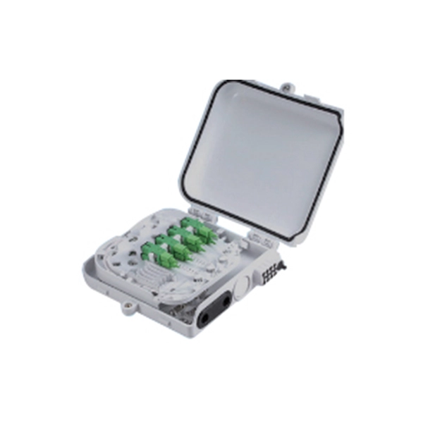
Calculate and select the right number and spacing of cables for junction boxes using NEC guidelines to ensure safe, code-compliant electrical installations. Electrical clearances set the minimum safe distances for panels, overhead lines, pools, and buried wiring — and ignoring them has real consequences. 7* Class A and Class X circuits using physical conductors (e., metallic, optical fiber) shall be installed such that the outgoing and return conductors, exiting from and returning to the control unit, respectively, are routed separately. The outgoing and return (redundant) circuit conductors. Above finished grade or sidewalks, or from any platform or projection from which they might be reached. (If these areas are accessible to other than pedestrian traffic, then one of the other conditions applies). This step keeps your project safe and. In this guide, we'll break down everything you need to know to install a distribution box correctly and confidently. Choose the right box based on environment (indoor/outdoor), load capacity, and durability. Check for proper IP/NEMA ratings and material quality. Ensure safe placement: install in. When looking into electrical panel clearance safety, you need to start by looking at the requirements put in place by the national electric code, or NEC. The relevant section of the national electric code here is NEC 110. This set of code identifies how much clearance is needed around any type.
[PDF]
Oxygen and acetylene cylinders must be stored at least 20 feet apart, or separated by a noncombustible barrier at least 5 feet tall with a minimum half-hour fire-resistance rating. Learn how OSHA requires you to store oxygen and acetylene cylinders safely, including separation distances, indoor limits, and handling empty tanks. 253 is the federal rule for oxygen-fuel gas welding and cutting in general industry. It sits in 29 CFR 1910 Subpart Q alongside three sister sections: 1910. 251 (definitions), 1910. 252 (general welding — fire prevention, PPE, ventilation, confined spaces), 1910. 254 (arc welding). Alternatively, there is no requirement for space between flammable and oxidizing gases if a minimum 5ft. This code review also outlines other important and relevant information. information, refer to the Compressed Gas Association (CGA) for Pamphlet P-1. Always separate gases by type and keep them in assigned, clearly identified locations. OSHA requires that cylinders containing flammable gases are either stored at least 20 feet (6. 1m) feet from highly combustible materials such as oil or excelsior. Cylinders should be stored in definitely assigned places away from elevators, stairs, or gangways. (b) The distribution piping must include a means, located as close to the supply cylinders as possible, of regulating the discharge pressure from the supply.
[PDF]
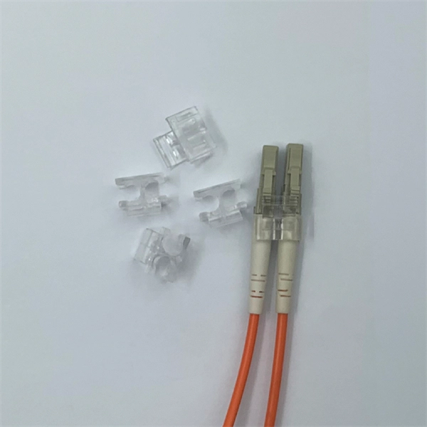
If an optical module is installed in a running router, you can run the display transceiver command to view parameters of the optical module, including the center wavelength, transmission distance, fiber types supported, receive optical power, and transmit optical power. Some users may be ambivalent about the measurement of an optical module's transmission distance in practice. If you are one of them, find out the methods in this article now! 1. Working Wavelength 3. Compliant Protocols & Standards 5. An SFP (Small Form-factor Pluggable) module transmits data over fiber using specific wavelengths and power levels, which directly influence how far the signal can travel before degradation occurs. Unchecked optical modules can cause: Testing ensures compliance with IEEE 802. 3 and MSA. An OTDR (Optical Time Domain Reflectometer) is a measuring instrument intended to measure the transmission loss and distance of optical fibers, locate cable cuts, and evaluate the connection loss and reflectance (return loss) of fusion splices, mechanical splices, connector connections, etc. These fibers are most commonly made of glass and are very thin, typically less than a tenth of the width of a human hair. Fiber optic cable.
[PDF]
Fiber optic cable can be run anywhere from 300 meters up to 80 kilometers (roughly 50 miles) depending on the cable type, transceiver used, and network standard. For most enterprise or data center applications using multimode fiber, the practical limit sits between 300 m and 550 m. Fiber optic cables are the backbone of modern communications, enabling high-speed data transfer over vast distances. Unlike traditional copper cables, fiber optic cables use light to transmit data, resulting in faster speeds and greater bandwidth capabilities. However, fiber optic cable performance. With ideal conditions and amplification, optical fiber can transmit petabit speeds globally, but real-world limits depend on fiber type and network design. Single-mode. Fiber optic transmission distance varies based on fiber type, environmental conditions, and equipment selection. This guide explores the key factors affecting fiber optic transmission distance and provides practical selection guidelines for a stable and cost-effective network deployment. Dispersion. General Symmetric cable pairs Land coaxial cable pairs Submarine cables Free space optical systems G. 649 Optical fibre cables G. 659 Characteristics of optical components and subsystems Characteristics of optical systems G. Attenuation is the progressive loss of signal strength that occurs as light travels through the fiber. The greater the distance, the greater.
[PDF]
The Optical Time Domain Reflectometer (OTDR) is useful for testing the integrity of fiber optic cables. It can verify splice loss, measure length and find faults. in cable TV, LAN, metropolitan networks or long-haul. Ensure the integrity of your fiber optic network with an Optical Time Domain Reflectometer (OTDR). OTDR testing analyzes fiber optic cable performance from end to end by testing components along the cable, including connection points, bends, and splices. It injects a series of optical pulses into the fiber and analyzes the backscattered signal based on time, enabling a detailed view of the. 15 EXFO Inc. No part of this publication may be reproduced, stored in a retrieval system or transmitted in any form, be it electronically, mechanically, or by any other means such as photocopying, recording or otherwise, without the prior writt eved to be accurate and reliable. From a single end of the link, it can determine the magnitude and location of loss, detect reflections, and visualize events along the fiber. An OTDR injects a series of optical.
[PDF]
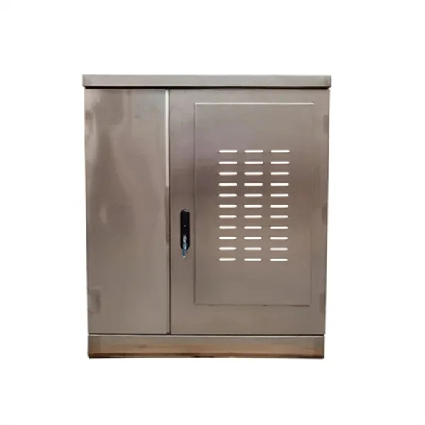
From 42u to 48u, our seismic server racks and cabinets can hold their own against the Earth. Need additional stability, consider adding optional bolts or brackets for reinforcement. NEBS GR 63-Core certified zone 4 cabinets for earthquake prone or areas subject to regular vibrations, such as airports, factories and high rise buildings. Solid sided construction, 2 pair of fully adjustable mounting rails, Seismic bolt down base with cable access holes, top panel with cable. Discover premium seismic racks at Server Racks Online, engineered to protect your critical equipment in earthquake-prone and high-vibration environments. Our seismic racks meet strict industry standards, offering robust construction and enhanced stability to safeguard IT, server, and network. SR42UBZ has been designed and tested to meet Telcordia GR-63-CORE Network Equipment & Building Systems (NEBS) requirements for Zone 4 Seismic Earthquake Environments. It is designed for secure, high density server and networking applications in IT environments that are earthquake prone or subject. EnviroGuard's Rack Series seismic flooded battery racks conform to UBC standards and are certified to meet IBC 2012 standards for essential facility applications. Designed with provisions. Emcor's seismic qualified enclosures are designed to meet or exceed the Telcordia NEBS Zone 4 testing objectives and earthquake requirements.
[PDF]