Calculate and select the right number and spacing of cables for junction boxes using NEC guidelines to ensure safe, code-compliant electrical installations. Electrical clearances set the minimum safe distances for panels, overhead lines, pools, and buried wiring — and ignoring them has real consequences. 7* Class A and Class X circuits using physical conductors (e., metallic, optical fiber) shall be installed such that the outgoing and return conductors, exiting from and returning to the control unit, respectively, are routed separately. The outgoing and return (redundant) circuit conductors. Above finished grade or sidewalks, or from any platform or projection from which they might be reached. (If these areas are accessible to other than pedestrian traffic, then one of the other conditions applies). This step keeps your project safe and. In this guide, we'll break down everything you need to know to install a distribution box correctly and confidently. Choose the right box based on environment (indoor/outdoor), load capacity, and durability. Check for proper IP/NEMA ratings and material quality. Ensure safe placement: install in. When looking into electrical panel clearance safety, you need to start by looking at the requirements put in place by the national electric code, or NEC. The relevant section of the national electric code here is NEC 110. This set of code identifies how much clearance is needed around any type.
[PDF]
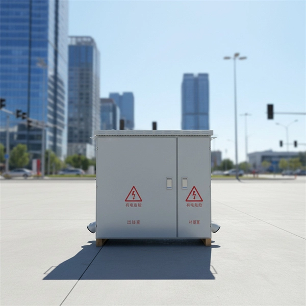
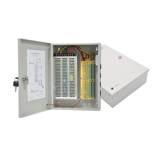
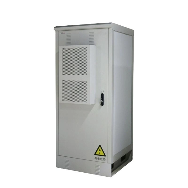
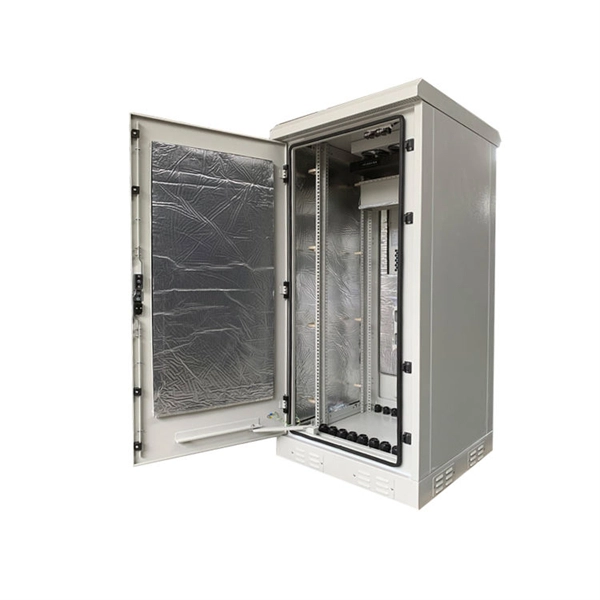
Ensure safe placement: install in dry, accessible areas with good ventilation and at appropriate height (typically ~1. Practice good wiring: secure grounding, neat cable management, proper insulation, and correct wire gauge and breaker size. Include protection devices like breakers, fuses, and. The National Electrical Code (NEC) requirements might seem like bureaucratic red tape, but they're more like the safety rails that keep everything running smoothly and prevent dangerous surprises. "Getting your distribution box installation right isn't just about passing inspection - it's about. Strictly speaking, the word “Distribution Box (D-box)” can refer to two categories: electrical distribution boxes and septic tank distribution boxes. This article mainly talks about the first one. An electrical distribution box, also known as a power distribution box, panelboard, or consumer unit. NEC (National Electrical Code) Article 314 provides strict requirements for these installations, and for good reason. This guide breaks down everything homeowners need to know about outdoor electrical junction boxes in plain English. You'll learn what they are, why they're required, the difference. The installation requirements and specifications of Distribution box involve many aspects, including site selection, fixing method, wiring specifications and safety protection. Whether it is residential buildings, commercial facilities or industrial sites, the.
[PDF]
Underground fiber optic cable installation follows specific standards that govern burial depth, testing methods, installation techniques, and safety requirements. Underground cables are pulled in conduit that is buried underground, usually 1-1. 2 meters (3-4 feet) deep to reduce the likelihood of accidentally being dug up. In extreme cold climates, cables may need to be buried at greater depths where there temperatures are colder and frost penetrates to. The Fiber Optic Association, Inc. (FOA) was founded in 1995 to help develop the workforce to build the fiber optic networks to support a rapid expansion in communications and the Internet. The charter of the FOA was to promote professionalism in fiber optics through education, certification, and. This guide walks through each stage of underground fiber installation—from route planning and conduit selection to splicing, termination, and testing—to help ensure long-term network performance and reliability. These standards, established by organizations like the National Electrical Code (NEC), National Electrical Safety Code (NESC), and. Installing underground fiber optic cables is critical to establishing high speed internet infrastructure that delivers reliable connectivity for businesses nationwide. Unlike traditional copper systems, fiber optic cables require specialized handling techniques and precise installation methods to.
[PDF]
This document outlines the Philippine Electrical Code (PEC) and its regulatory framework, including laws, objectives, and standards for electrical installations. It emphasizes safety, compliance, and the roles of various government authorities in enforcing these regulations. The Philippine Electrical Code (PEC) is a set of standards and regulations that govern the safe and proper installation, operation, and maintenance of electrical systems in the Philippines. It provides guidelines for electrical design, wiring, equipment selection, grounding, protection, and other. Members of each committee meet several times, discuss proposed changes, accepting some and rejecting others, and rewrite (as required) the sections of the Code that were assigned to their committee. ❑ Regularly revised (every three years) to reflect the evolution of products, materials, and. The purpose of this Code is the practical safeguarding of persons and property from hazards arising from the use of electricity. This Code contains provisions that are considered minimum requirements necessary for safety. Compliance therewith and proper maintenance will result in an. ALL ELECTRICAL WORKS HERE IN SHALL BE EXECUTED IN ACCORDANCE WITH THE LATEST EDITION OF THE PHILIPPINE ELECTRICAL CODE (PEC). THE NEW ELECTRICAL ENGINEERING LAW (R. LAWS AND ORDINANCES OF THE LOCAL GOVERNMENT UNIT AND RULES AND REGULATIONS OF THE LOCAL ELECTRICAL POWER UTILITY COMPANY. Philippine Electrical.
[PDF]
Every protection system which isolates a faulty element is required to satisfy four basic requirements: (i) reliability; (ii) selectively; (iii) sensitivity; and (iv) speed of operation. Protection system is an extremely important part of the power system as it is provided to operate under abnormal conditions to prevent failure or isolate trouble and limit its effect. It is designed to detect and isolate faults or abnormal conditions within the system to prevent damage, minimize downtime, and maintain power quality. This. Relay protection primarily operates on the principle of utilizing the variations in electrical quantities (such as current, voltage, power, frequency, etc. It emphasizes selectivity, coordination, fault response, and system behavior rather than individual relay devices. Relay protection is often misunderstood as a. Protective relays and devices have been developed over 100 years ago to provide “lastline”of defense for the electrical systems. They are intended to quickly identify a fault and isolate it so the balance of the system continue to run under normal conditions. The selection and applications of. Abstract: Information on the concepts of protection of ac transmission lines is presented in this guide. Many important issues, such as coordination of settings, operating times, characteristics of.
[PDF]
We recommend a 'clear space' of 3 ½ inches high, and 4 inches wide on self-mailer pieces. This space is used to display the delivery address, postage, and return address. For folded self-mailers, the fold must be on the bottom or leading edge of the piece. According to the USPS mailing requirements, you have a standard range of dimensions for all your self-mailers. The standard sizes for your self-mailers are mentioned in the table below. Note: It is worth noting that it is okay for your business to use a self-mailer with 0. 009 thickness as long as. The NEC requirements for flush-mounted box installations can be found in Sec. First-Class Mail: 13 ounces. Periodicals: 20 ounces for pieces prepared under 201. A conduit body is a removable-cover section of a conduit system that provides access at junctions or termination points. Article 314 applies to: These. Done right, it ensures safety, compliance, and long-lasting performance. In this guide, we'll break down everything you need to know to install a distribution box correctly and confidently. Choose the right box based on environment (indoor/outdoor), load capacity, and durability. Check for proper. for disconnects, and meter socket enclosures. Notice that these rules cover the cabinets and enclosures that contain electrical equipment su h as panel boards— not the equipment itself ided with a fra for disconnect d telescoping w rfere with succes rs hub, or conn more than 1⁄4 in.
[PDF]
In this article, we'll explore the best practices for installing and maintaining fiber optic cables in data centers, ensuring optimal performance, reliability, and scalability for years to come. Master data center fiber optic implementation with detailed technical specifications, installation procedures, and optimization strategies. Explore advanced configurations, testing protocols, and industry best practices. Modern data centers represent the pinnacle of fiber optic technology. As data centers continue to grow in complexity and scale, efficient fiber optic cabling is essential for maintaining high performance, reliability, and scalability. You'll learn how to: Disorganized cabling creates direct financial consequences. Before a single cable is laid, thorough planning and design are crucial for a successful fiber optic. The Fiber Optic Association, Inc. (FOA) was founded in 1995 to help develop the workforce to build the fiber optic networks to support a rapid expansion in communications and the Internet. The charter of the FOA was to promote professionalism in fiber optics through education, certification, and.
[PDF]
The corrosion resistance of the cable trays is based on the UNE-EN IEC 61537 standard and is verified by the continuous salt spray test (ISO 9227). Both procedures are certified and audited by AENOR, which guarantees full compliance with national and international standards. This guide provides detailed insights into preventing corrosion and extending the lifespan of cable trays. Corrosion can weaken cable trays, leading to failures that disrupt operations and pose safety risks. This treatment is ideal for environments requiring: Selecting the right Cable Trays Surface Treatment depends on several factors: Environmental Conditions: Evaluate exposure to moisture, chemicals, UV, or extreme temperatures. Budget Constraints: Balance performance requirements with cost. This white paper compares the High Resistance (HR) and Hot-Dip Galvanising (HDG) solutions and highlights the new High Resistance range, ZnAl wiremesh, ZnMg metal cable trays and accessories and ZnNi screws and bolts. Presentation pictures do not always include Personal Protective Equipment (PPE). association representing the major electrical equipment manufac-turers in the U. The protection classes. Cable trays are often exposed to: Without proper protection, corrosion can lead to: A corroded cable tray is not just a maintenance issue — it is a safety risk. Choosing the right finish depends on the installation environment. The most commonly used options are: GI trays are made from.
[PDF]
The generally accepted and code-compliant height for switches is typically 48 inches (4 feet) from the finished floor to the top of the switch box. This standard helps ensure accessibility and consistency across installations. While the National Electrical Code (NEC) doesn't specify a mandatory standard outlet height for most general-use receptacles, established industry best practices and accessibility laws provide clear guidance. The NEC (Article 210. 52) specifies where receptacles must be placed (spacing along walls, required. The commercial electrical code requires switches at 42 to 48 inches and receptacles at 18 inches above finished floor in most applications. This height is an ergonomic choice, aligning well with the average reach.
[PDF]
Generally, standard trays require supports every 6 to 10 feet, while heavy-duty, long-span trays can handle distances of up to 20 feet between supports. To determine the proper spacing, consult the manufacturer's load capacity chart, which accounts for the total weight of the. The following are a few points to consider when dealing with cable tray and the National Electrical Code. This is a description of how to select, install, and support these metal or plastic frames, on which electrical wires are installed. You should consider it as a series of instructions that make the buildings resistant to. Support spacing for cable trays must align with the manufacturer's instructions, as outlined in NEC 392. This spacing is crucial for adequate maintenance access, ease of inspection, and ensuring proper airflow for effective heat dissipation. It also helps reduce the risk of. In this installment of our Code Corner series, Ryan Mayfield focuses on the 2023 National Electrical Code (NEC) changes concerning cable trays, particularly section 690. Historically, the NEC has allowed cable trays, but has lacked specific guidelines for sizing conductors and using smaller. This guide covers the critical steps, from selecting the right electrical cable tray and performing accurate cable fill calculations to managing a safe cable pull through and ensuring all bonding and grounding requirements are met. For licensed electricians, mastering these principles is essential.
[PDF]