BMPT-62 (sometimes called Algerian Terminator in reference to the BMPT Terminator) – A fire support vehicle developed from leftover T-62 tanks and Berezhok turrets. The vehicle was presented at the 60th anniversary parade of Algeria's independence. the BMPT-62 is a fire support fighting vehicle specific to Algeria, often nicknamed locally "Mini Terminator". This is not a standard Sovie. TypeFire Support Combat Vehicle (Tank support combat vehicle) · Place of originIn service2010s–presentUsed byDevelopmentThe concept of the BMPT-62 was born out of 's desire to have a tank support vehicle similar to the Russian "Terminator" (which Algeria also has in active service). The development was carried out. The concept of converting retired T-62 main battle tanks into fire support vehicles emerged from the Algerian Army's logistics and upgrade experience with the Russian-made Berezhok turret system. Algerian engineers.
[PDF]
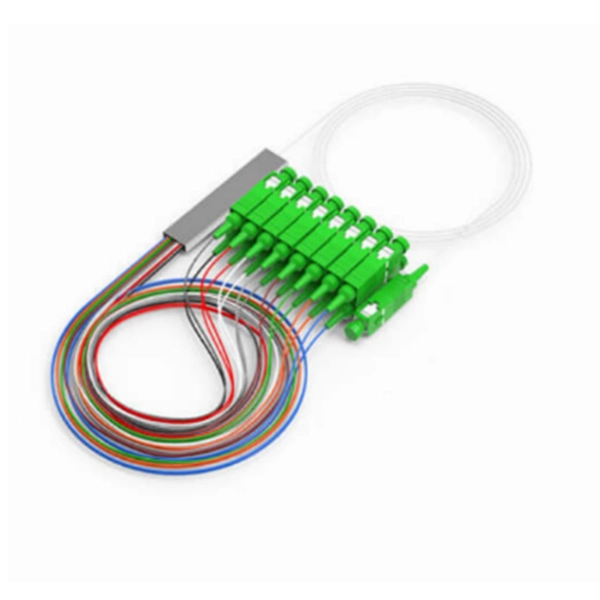
ITU & IEC allow 0. 75 dB loss per mated pair. Splitter loss values are "Typical" and include a connector in and out. These values are approximate and should not be exceeded by more than 1-1. 5 dB, which could indicate dirty connectors, bad splices . ITU & IEC allow 0. Passive split links usually lose the most dB at the splitter, so we keep the optical budget and the installed route separate. Measured in feet for imperial mode. Drop length Adds. Calculate split loss, excess loss, and terminations for any ratio quickly today. See power budget impact instantly, then download a CSV or PDF summary. Use 2×N when two inputs feed the same distribution stage. Common values: 2, 4, 8, 16, 32, 64. Abridged Optics — Beam Splitter Calculatorv1. 0Fresnel calculations assume a single uncoated interface. Real beam splitters use multi-layer coatings that modify R/T beyond Fresnel predictions. Understanding the types of splitters, their impact on network performance, and how to measure their losses ensures high-quality network operation and facilitates optimal splitter selection based on. This value should be determined by the system designer. 3 recommends a maximum value of 0. Total Splice Loss (The maximum splice loss permitted for installation. Components, such as fiber cables, splitters, and switches, introduce attenuation.
[PDF]
Attenuation is the natural loss of signal power over distance. This is inherent in all fiber types and happens even under ideal conditions. Factors such as wavelength and fiber quality influence attenuation. At shorter wavelengths like 850nm, attenuation is higher, especially in. To be able to judge whether a fiber optic cable plant is good, one does a insertion loss test with a light source and power meter and compares that to an estimate of what is a reasonable loss for that cable plant. The estimate, called a "loss budget" is calculated using typical component losses for. A significant signal loss in the optical fiber can cause unreliable transmission. How can we know the value of losses on the fiber link? Read on, this post will teach you how to calculate the losses in optical fiber and judge the fiber link performance. What is optical fiber loss? Fiber loss can be. At TREND Networks, we are frequently asked how much loss is allowed when conducting testing on fiber optic cabling. So how do you determine acceptable loss? When testing fiber optic cabling, determining acceptable loss is. Understanding fiber loss is vital in maintaining a reliable, efficient network. While some loss is expected, excessive or unexpected loss can lead to poor performance, network. Optical fiber loss is a term for signal loss affecting transmission reliability. So how is the fiber attenuation calculation? 1, ODN full attenuation accounting: According to the worst value.
[PDF]
This document describes how to use and program the Photonic Application Suite, Insertion Loss Engine. Insertion loss is measured by comparing signal power (or sound level) before and after it passes through a component or system, then expressing the difference in decibels (dB). The core process is the same across fiber optics, RF electronics, and acoustics: establish a baseline reference without. This tutorial aims to help RF engineers understand how to test and measure various RF specifications of RF power amplifiers, RF LNAs (Low-Noise Amplifiers), and RF transceivers using RF test and measurement equipment like spectrum analyzers, signal generators, and sweep oscillators. Gain is the. Coaxial cables are essential components in transmitting radio frequency (RF) signals, but they inherently attenuate these signals, a phenomenon known as cable loss or insertion loss. Yes, I would like to receive educational or promotional emails from Keysight. By clicking the button, you. Insertion loss is a critical parameter in RF engineering that refers to the loss of signal power that occurs when a component or device is inserted into a transmission line or circuit. The insertion loss measurement quantifies the effect of the resistance the cabling link offers to the transmission of the electrical signals. Insertion loss characteristics of a.
[PDF]
For singlemode fiber, the loss is about 0. 5 dB per km for 1310 nm sources, 0. 5 dB/km at either wavelength for outside plant max per EIA/TIA 568)This roughly translates into a loss of 0. 1. To be able to judge whether a fiber optic cable plant is good, one does a insertion loss test with a light source and power meter and compares that to an estimate of what is a reasonable loss for that cable plant. The estimate, called a "loss budget" is calculated using typical component losses for. Manufacturers provide a fiber loss factor in dB per kilometer. Total fiber loss is calculated by multiplying the distance by the loss factor, considering the actual cable length. 25 dB/km (@1550nm) and 0. Understanding where those losses come from, and how to calculate them, is essential for designing a link that actually works. The decibel is. A loss budget in fibre optics is a detailed accounting of every potential source of signal attenuation (loss) in a fibre optic link. By accurately calculating and managing loss budgets, engineers and technicians can guarantee that optical signals reach their destination with enough power to be. After measuring the loss of a fiber link, you now have to determine if that fiber link loss is acceptable or not. Here are the details and instructions about each field and how they contribute to the calculation: 1. Attenuation Coefficient (dB/km): This value represents the inherent signal loss per kilometer of.
[PDF]
The devices has a wide pass band, low insertion loss, high channel isolation and excellent environmental stability. Channel numbers can be as high as 40 (16) for 100 (200)GHZ systems in C band or in L band. They can be used in DWDM systems to perform a multiplexing or. Fiberdyne Labs offers Dense Wavelength Division Multiplexer (DWDM) Modules in a wide variety of formats. While Fiberdyne offers some models as "standard," we will also produce customized DWDM modules. Customization can include the number and selection of DWDM channels. Channel. AFL's DWDM LGX modules provide scalable wavelength management for new deployments and network upgrades, providing increased bandwidth over a single common fiber. Based on thin film filter technology, the device is less than one-third the size of traditional cascaded DWDMs of similar channel count. Modules can be installed in standard LGX chassis and are available with LC bulkheads in select. All parameters are for device without connectors 2. Special specifications can be customized according to customer requirements DWDM mux demux and optical modules for high-capacity fiber networks. 40/80-channel options, rack mount or LGX type, low insertion loss, high stability. Ideal for telecom.
[PDF]
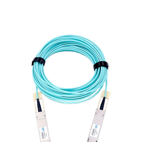
The QSFP28 transceiver provides 100GBase-BX throughput up to 20km over single-mode fiber (SMF) using a wavelength of 1310nmTx/1280nmRx via an LC connector. This bidirectional unit must be used with another transceiver or network appliance of complimenting wavelengths. Whether it's building a network or upgrading an existing network, the Cisco® QSFP-100G-B20U4-I and QSFP-100G-B20D4-I transceivers provide 100G connectivity for platforms at up to 20km on single SMF (Single Mode Fiber). This. The QSFP-100G modules are our latest generation of 100G transceiver modules solution based on a QSFP form factor. Table 1 describes the Cisco QSFP-100G portfolio. Cisco QSFP-100G Portfolio The Cisco 100GBASE-SR4-S QSFP Module supports link lengths of up to 70m. To meet the demand for long-distance transmission in scenarios where optical fiber resources are scarce in edge access networks, Walsun has launched the 100G QSFP28 ZR4 BIDI product, and will demonstrate 100G 80km single-fiber bidirectional service transmission at OFC 2024. 66nm-RX) via an LC. NEC's 100G QSFP28 BiDi optical transceiver enables the transmission and reception of 100Gb/s high-speed data over a single optical fiber. By enabling bidirectional transmission over a single fiber, this module enhances fiber utilization efficiency and can reduce fiber costs. ZR4 BiDi, using four.
[PDF]
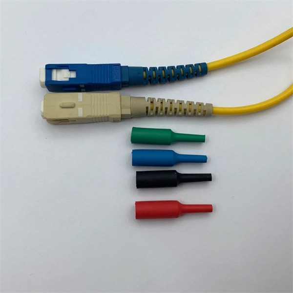
To connect an optical cable to an SFP module, use the appropriate patch cord (e., LC-LC, SC-LC, etc. The patch cord must match the fibre type – single-mode or multi-mode. Once connected, verify that the port activity indicator is on and run diagnostic commands to check the. Small Form-factor Pluggable modules (SFP module) are the workhorses of modern network connectivity, enabling flexible fiber optic or copper links between switches, routers, firewalls, and servers. Whether you're upgrading bandwidth, replacing a faulty unit, or reconfiguring your topology, knowing. Connecting your fiber optic cable to an SFP (Small Form-factor Pluggable) module can seem daunting if you're unfamiliar with networking hardware. However, with a bit of guidance, the process is straightforward. Remove the dust caps from the SFP module and the fiber optic cable. Today, we will discuss the best methods to connect SFP to fiber optic patch cables. To connect a fiber optic cable to SFP optical module, first ensure the SFP is fully inserted into the network port until it "clicks", then remove the dust caps from both the SFP and the LC fiber optic connector. Laser Compliance The fiber-optic SFP+ / SFP28 modules contain a laser that is classified as a “Class 1 Laser Product” in accordance with US FDA regulations and the IEC 60825-1. The product does not emit hazardous laser radiation. The module is fully seated when you hear a click. (SFP+ and SFP28.
[PDF]
This paper discusses some practical aspects of implementing single-pole tripping schemes in transmission-line protection. Implementation and techniques will vary in the design of protective relaying systems that i.
[PDF]
FSPF is the protocol currently standardized by the T11 committee for routing in Fibre Channel networks. The FSPF protocol has the following characteristics and features: Supports multipath routing. Bases path status on a link state protocol. Routes hop by hop, based only on the. Fabric Shortest Path First (FSPF) is the standard path selection protocol used by Fibre Channel fabrics. Except in configurations that require special consideration, you do not need to. Fibre Channel (FC) is a high-speed data transfer protocol providing in-order, lossless delivery of raw block data. Fibre Channel is primarily used to connect computer data storage to servers in storage area networks (SAN) in commercial data centers. Fibre Channel networks form a. Fibre Channel Routing (FCR) connects two or more fabrics without merging the fabrics. The fabric that contains the FC router is known as the backbone fabric. An edge fabric is a standard Fibre Channel fabric with targets and. “The Fibre Channel Industry Association (FCIA) is a mutual benefit, non-profit, international organization of manufacturers, system integrators, developers, vendors, industry professionals, and end users. In a SAN, the backbone fabric consists of at least one FC router and possibly a number of Fabric OS-based Fibre Channel switches. The link between an E_Port and EX_Port, is called an inter-fabric link (IFL).
[PDF]
Integrated optical switching delay line (OSDL) chip, which is composed of optical switches cascaded with optical waveguides of different lengths, has the merits of ultra-wide delay bandwidth, very high delay accu.
[PDF]
Acceptable dB loss for fiber depends on the component you're measuring: a single mated connector pair should lose no more than 0. 75 dB, a fusion splice should stay under 0. 3 dB, and fiber cable itself loses between 0. To be able to judge whether a fiber optic cable plant is good, one does a insertion loss test with a light source and power meter and compares that to an estimate of what is a reasonable loss for that cable plant. The estimate, called a "loss budget" is calculated using typical component losses for. Q: What is fiber optic loss? A: Fiber optic loss refers to the reduction in signal strength as it travels through the fiber optic cable. This can be due to various factors, including attenuation, connectors, and splices. Q: How is fiber optic loss measured? A: Fiber optic loss is typically measured. Fiber loss can be also called fiber optic attenuation or attenuation loss, which measures the amount of light loss between input and output. 5 dB per kilometer depending on the type and wavelength. The total. Attenuation is the natural loss of signal power over distance. This is inherent in all fiber types and happens even under ideal conditions. Factors such as wavelength and fiber quality influence attenuation. Measured in decibels (dB), loss degrades signal quality, limits distance, increases bit-error rate, and escalates infrastructure cost. Understanding and managing it is critical to.
[PDF]
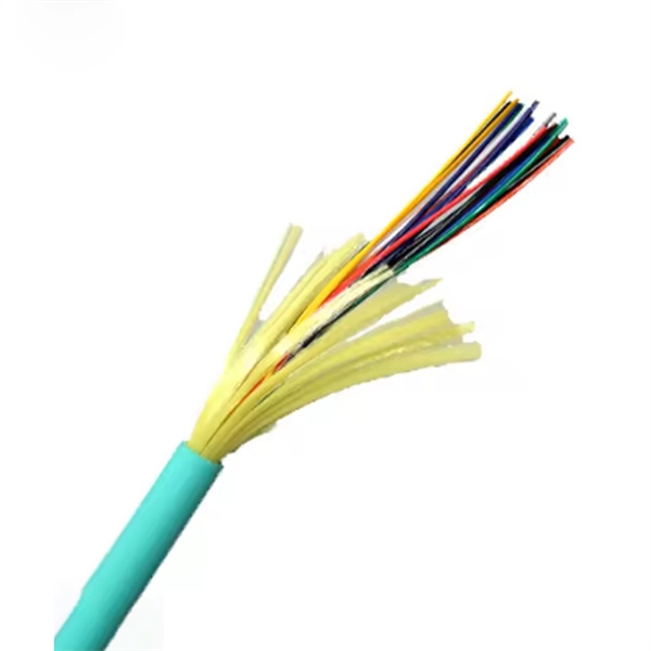
Connecting a multi-mode SFP to single-mode fiber creates a major signal mismatch. A small portion of the transmitted light gets captured. This leads to high attenuation and frequent link drops. I suggest you avoid such setups. Use them if essential and with proper mode conditioning. But what happens when you need to connect an existing multi-mode campus network to a new single-mode service provider link? You can't just splice them together. This is where fiber conversion comes in. This guide will break down the professional methods to achieve seamless single-mode to multi-mode. A fiber optic cable or optical fiber cable is a medium used for transmitting optical signals from one place to another. It consists of a strand of glass fibers inside an insulated casing. Fiber optic cable comprises a core, cladding, and a buffer. I've seen people use a single-mode. But not all fiber cables are created equal: multimode (MM) and single mode (SM) fibers are the two primary types, each engineered for specific use cases, from short-range data center connections to transcontinental telecom backbones. This type of patch cord helps to transfer the single mode signal into a multimode signal by aligning the two different types of fibers. However, it's important to note that this method may have. Multimode fiber cabling is used for indoor, short distance applications and single-mode fiber cabling is used for outdoor, long distance application.
[PDF]
This article provides an in-depth exploration of OSFP copper cable technologies, including DAC, ACC, and AEC, with a focus on 400GB NDR splitter cable applications. Whether the signal is propagated by copper wire, optical fiber, Wi-Fi, or just yelling at the kids down the street, the signal is never as strong at the destination as it is at the source. In the case of physical voice communication, the kids will understand you if they are close-by. If they are. Insertion loss and attenuation are similar concepts, but one is assigned to a single component (insertion loss) whereas the other is assigned to generalized performance (attenuation). Both terms refer to a measurement comparing the signal strength received against a transmitted signal. Standard. Channel Master TV splitters are designed to equally divide the signals on the input port of the splitter to each of the output ports of the splitter. This. Insertion loss is the amount of energy that a signal loses as it travels along a cable link. It is a natural phenomenon that occurs for any type of transmission—whether it's electricity or data. This reduction of signal, also called attenuation, is directly related to the length of a cable—the. In fiber-optic networks like FTTx and PON, PLC splitters are key components for distributing optical signals to multiple users. However, each splitter has complex parameters, including insertion loss, return loss, polarization-dependent loss, and uniformity.
[PDF]