Welcome to our light sources category, where we offer advanced calibration solutions designed for precision and accuracy in scientific measurements. Our selection encompasses two primary subcategories: “Wavelength Calibration” and “Radiometric Calibration,” featuring state-of-the-art products. This. As a result of a 2-year research project, finalised in 2020, GL Optic developed new calibration facilities and created Calibration and Research Laboratory of Optical Radiation ( CARLO ). Today, CARLO is the only laboratory in Central and Eastern Europe equipped with the Black Body Radiator – the. We offer two types of light sources for calibration: Pen-Ray line sources for the wavelength calibration of spectroscopic instruments and calibrated irradiance sources covering UV-NIR. All Avantes spectrometers are factory wavelength calibrated and do not require recalibration as they have fixed slits and optics. Options include mercury-argon (253-1700 nm), krypton (427-893 nm), neon (540-754 nm), argon (696-1704 nm) and xenon (916-1984 nm) gas-discharge emission sources. Multiple LED sources can be efficiently combined into a single output beam, and offer major advantages such as long life-time, easily tunable spectrum, high power stability, and ultra-fast switching (on the microseconds level) without using moving mechanical components. Multi-Wavelength Collimated.
[PDF]
When the LOS light turns red or blinks red, it usually means your ONT or fiber router is not receiving the optical signal properly from the network. In most cases, this is not just a normal WiFi issue. It usually points to a signal-side or line-side problem rather than a small. The LOS light on your router indicates the status of your internet connection to the Internet Service Provider (ISP). When it's green and steady, everything is fine. Fortunately, diagnosing and resolving these issues doesn't have to be complicated. In this comprehensive guide, we will walk you. Whether your modem is blinking orange, your router has a solid red light, or you are staring at a mysterious "DS" indicator, you will find the answer below. A solid green or white light on your modem or router almost always means everything is working normally. You might feel like you're staring into the abyss of digital darkness, wondering what went wrong. Before you panic or call tech support, there are several simple fixes you can try at home that often solve this problem in minutes. Existing Krishii Fiber customers can share their registered mobile number, area and a.
[PDF]
It enables uniform, shadow-free lighting by directing light along the same optical axis as the lens. When integrated into specialised lenses, the beam splitter divides the incoming light into two paths: one beam illuminates the object, while the other is used for image capture. Beamsplitters are fundamental components in optical engineering, serving to precisely divide a single input beam of light into two distinct output beams. This division allows for the simultaneous analysis or utilization of the light's properties along two separate paths. Additionally, beamsplitters can be used in reverse to combine two different beams into a single one. In practice, the reflective layer absorbs some light. It is a crucial part of many optical experimental and measurement systems. A cube beam splitter is, at its essence, an optical device that splits an incoming light beam into two sections. What are beamsplitters and how are they used in optics and photonics applications ? Beamsplitters are optical components that are used to. The beam splitter splits and then recombines infrared radiation, while the detector picks up the resulting signal. It's sensitive to both intensity and frequency. Together, they decide just how accurately an instrument captures those unique infrared “fingerprints” from different substances.
[PDF]
Your eyes contain two types of light-sensing cells: rods and cones. Rods detect low-light vision and motion, while cones handle color vision and detail in bright light. Damage to either can lead to vision problems like night blindness or color blindness. Protecting your eyes with proper nutrition. Personnel Safety. Optical Touch Buttons. Self-contained Sensors. Each technology has unique strengths and weaknesses, so the requirements of the application itself will determine what technology should be used. This article is focused on photoelectric sensors and defines what they are, their adv ors are readily present. Quality Control: They can detect defects, ensure proper product placement, and verify the presence of components. Safety: They can be used to create safety barriers, preventing machinery from operating when a person or object is in a hazardous zone. In this section, we explore the geometric optics of the eye. Early thinkers had a wide array of theories regarding vision. Euclid and Ptolemy believed that the eyes emitted rays of light;. Understanding the eye involves examining how its individual parts contribute to the overall function. Vision begins as light enters the eye through the cornea, a transparent, dome-shaped outer.
[PDF]
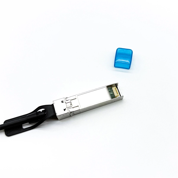
Singlemode fiber features a small core diameter of just 9 µm and allows only one mode of light to propagate. This design minimizes signal loss and supports high-bandwidth applications over long distances. 5 µm) with multiple light. Single-mode fibers (also called monomode fibers) are optical fibers which are designed such that they support only a single propagation mode (LP 01) per polarization direction for a given wavelength. Higher-order modes like LP 11, LP 20 etc. It allows just one light signal – typically lasers – to pass through at a time. This keeps the signal tight and strong, making it ideal for long. Optical Fiber comes in two main categories: singlemode and multimode. Singlemode fiber is designed for long-distance data transmission, typically over distances greater than 10 kilometers. Glass or plastic are often used to make these fibers. Metal wires are used in optical fibers because they protect against damage and are immune to electromagnetic interference. This characteristic allows for significantly less signal degradation and higher data rates over.
[PDF]
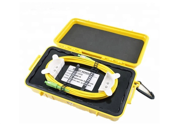
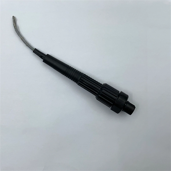
The worker must then connect one end of the fiber optic cable to a light source. Then, once they have done this they will turn on the light source and press the button on the. When it comes to testing fiber optic cables, a Visual Fault Locator (VFL) is an essential tool in your toolkit. A VFL is used to detect faults, breaks, or bends in fiber optic cables by emitting a bright red light that is visible even through the fiber's jacket. It's a cost-effective and. How to use fiber optic red light pen? It can be seen from the above that the red light pen has many uses, but its most common use is to detect the connectivity of the optical fiber and locate the fault point of the optical fiber. more How to use a VFL to identify a fiber optic cable from end to end. Viavi VFL:https://amzn. to/3L7cL6RTools I use:3 Hole Strippershttps://amzn. Within the pen, a small but powerful laser sends out an intense red light. Here is how the pen helps detect errors. If the fiber optic cable is appropriately intact and. The RPEN-210 is a necessity tool that should not be missing from any fiber plant manager or fiber optic installing technician. The Visual Fault Locator (VFL) Pen has a visible red light source centered on 650nm. Tool sends visible light over a fiber strand with a 10mW power, good enough to reach.
[PDF]
Check the electrical load and ensure that the sensors do not exceed the 10 Amp maximum. Check each wire for damage that may lead to a short. Check the following: Check if all cable connections are tightened with a torque moment of 14Nm (17Nm for the M10 model). Check if the surface area. Channel has NO voltage and there is an active fault. Check for tripped or missing circuit breaker Sticky fault on the channel. Sticky Fault - an indicator that a fault has occurred that will stay until the indicator has been cleared manually. Channel has NO. Each powernet distribution box (PNDB) on the vehicle provides up to 4 low amperage circuits (30 amp and less), and up to three high amperage circuits through midi fuses. The fuses are located behind a cover on the face of the PNDB. On vehicles equipped with a cab load disconnect switch (CLDS), the. I have the following issues, green light on shunt all red lights on distributor, no SOC on screen. Everything else is working great. In troubleshooting I removed all the fuses from the distributor just to see if the fuse lights would not illuminate red and get green power. Any. Show the control box indicator lights. Show the accessory response (or lack of response). For LED Light Kit issues, also provide a photo of the LED Y-cable (to confirm which version you have). Videos and photos are required to file warranty claims with the manufacturer.
[PDF]
This comprehensive guide will equip you with the knowledge and steps needed to safely test a lighting circuit using a multimeter. We will cover the essential safety precautions, different testing methods, interpreting the results, and troubleshooting common issues. Understanding the principles. Multimeters are versatile tools used by electricians and hobbyists alike to diagnose electrical problems and ensure the proper function of electrical devices. We'll explain how to measure AC and DC voltage, test for continuity, measure capacitance, measure frequency, and test diodes. Hence the 'multi'-'meter' (multiple measurement) name. The most basic things we measure are voltage. Here is a step-by-step guide on how to test a light fixture with a multimeter for beginners: Step 1: Turn Off the Power Before you begin testing the light fixture, it is crucial to turn off the power to the fixture at the circuit breaker. It's an indispensable tool for troubleshooting and maintaining electrical circuits. Different types of multimeters offer varying degrees of precision and. An easy way to test a light fixture is to remove the bulb and replace it with one that you know is working. If you don't happen to have a working bulb handy, you can use a light socket tester or test the fixture with a multimeter.
[PDF]
The Light Cube can be dyed using any color cube. Upon merging, it adopts the color of the cube used. Each dye attempt increases a dye counter, tracking how many times it's been recolored. 💡 Note: These items transform when fused with a Light Cube. The glow effect varies based on dye count. or if you want to see a video, then here: https://www. Each dye. This is a light cube DIY kit that you need to weld and assemble by yourself. The bottom plate comprises a circuit board and component parts. The 512 LED lights make up a stereo space. A variety of cool model showing a three-dimensional effect. It's better to watch in the night. Installation Manual:. 8x8x8 LED Cube Kit DIY Electronic Kit Soldering Project Kit, User Needs to Solder The LED, and The Displayed Content Can Be Modified. (GZT-64) Shop products from small. The dot matrix component features 25 RGB color light clusters, arranged in a 5x5 grid. Each individual light bead offers 16000K color variations, all of which can be controlled via an APP. When these 25 light beads come together, they provide an infinite array of color possibilities. It can craft some pretty decent weapons and it can make my favorite structure, Lantern! I hope you enjoy! :D. A light source has been placed inside to create interesting shadows. The pieces in this project can connect to each other without using any glue (however using glue.
[PDF]
The AOI impacts the amount of light being reflected and transmitted. For example, most plate beam splitters have an AOI of 45 degrees, which may limit those who need more flexibility. A beam splitter or beamsplitter is an optical device that splits a beam of light into a transmitted and a reflected beam. It is a crucial part of many optical experimental and measurement systems, such as interferometers, also finding widespread application in fibre optic telecommunications. a laser beam) into two (or sometimes more) beams, which may or may not have the same optical power (radiant flux). Their precision and versatility make them indispensable in a variety of scientific, industrial, and technological applications. Beamsplitters are often classified according to their construction: cube or plate. Beamsplitters are fundamental components in optical engineering, serving to precisely divide a single input beam of light into two distinct output beams. This division allows for the simultaneous analysis or utilization of the light's properties along two separate paths. The device is purely. The beam splitter splits and then recombines infrared radiation, while the detector picks up the resulting signal. It's sensitive to both intensity and frequency. Together, they decide just how accurately an instrument captures those unique infrared “fingerprints” from different substances.
[PDF]
Wavefront shaping enables precise control of light propagation through multimode fibers, facilitating diffraction-limited focusing for applications such as high-resolution single-fiber imaging and high-power fiber amplifiers. While the theoretical intensity enhancement at the focal point is. Light from a high-power laser diode is coupled into a multi-mode fiber (diam:100 um, NA = 0. A de-speckle unit can be turned on and off to reduce any speckles that appear after light leaving the multi-mode fiber. A collimating lens (CL) after the fiber collimates the light to a certain. We present laboratory measurements demonstrating how the output beam profile from multimode fiber can be affected by the beam entry angle. In some applications, an alternative beam distribution such as a top hat or donut is desired instead of the inherent Gaussian distribution provided by typical. Light transport in a highly multimode fiber exhibits complex behavior in space, time, frequency, and polarization, especially in the presence of mode coupling. The newly developed techniques of spatial wavefront shaping turn out to be highly suitable to harness such enormous complexity: a spatial. What are the conditions for efficiently launching light into a multimode fiber? What happens to the intensity profile of light during propagation in a multimode fiber? How do bending and other disturbances affect the output beam profile? What are the challenges of maintaining single-mode.
[PDF]