Gigabit is a decimal unit defined as per SI standard. 1 Gigabit = 1000 Megabits. The unit symbol for Gigabit is Gbit or Gb. Abbreviated as Gb, a gigabit is a method of measuring data transmission. When the "b" is uppercase, like GB, this refers to a gigabyte. What comes before a gigabit? What comes after a gigabit? Gigabit vs. other data measurements. What comes before a. Gigabit single-mode fiber optic module Common parameters of optical modules 1. Center wavelength 1) 850nm (MM, multi-mode, low cost, but short transmission distance, usually only 500M); 2) 1310nm (SM, single mode, large loss during transmission, small dispersion, generally used for transmission. In computer networking, Gigabit Ethernet (GbE or 1 GigE) is the transmission of Ethernet frames at a rate of a gigabit per second. The most popular variant, 1000BASE-T, is defined by the IEEE 802. It came into use in 1999 and has replaced Fast Ethernet in wired local networks due to. What is 1 Gig in Mbps? 1 Gigabit (Gb) is equal to 1000 Megabits (Mb). This conversion is important to understand because data transfer rates are commonly measured in Mbps, but many internet plans, network devices, and even transceivers are rated in Gbps. So. A gigabit (Gb) is a unit of digital information equal to 109 bits, or 1,000,000,000 bits. It uses the standard SI decimal prefix 'giga-'. It is important to distinguish.
[PDF]
The Optical Module Chip Base is a critical packaging platform designed to support core components such as laser chips, detector chips, and driver chips in high-speed optical communication modules. The primary optical communication devices used are optical modules and optical chips, which are essential for high-speed data transfer and network interconnection. It serves as a bridge between the chip and external optical fibers or circuit systems, ensuring. In the backbone of the global digital infrastructure, optical modules are the unsung heroes, converting electrical signals into pulses of light and back again, enabling the high-speed data transmission that powers the internet, cloud computing, and telecommunications. At the heart of every advanced. An optical module is a device that converts electrical signals into optical signals and vice versa. Among various optical module form factors, SFP (Small Form-Factor Pluggable).
[PDF]
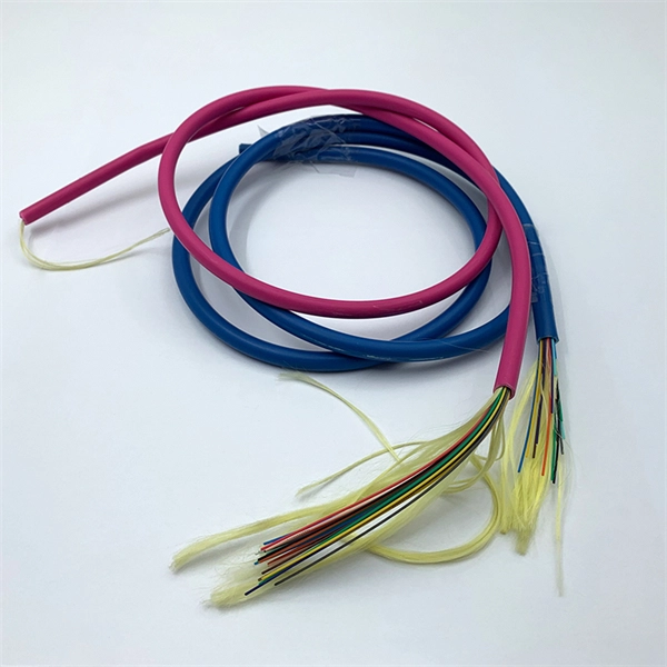
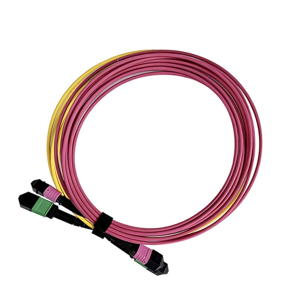
This step-by-step guide aims to provide a comprehensive understanding of the techniques and considerations involved in successfully connecting optical fibers, offering invaluable insights for professionals and enthusiasts in the field. In high-speed data networks, the seamless integration of fiber optic cables with SFP (Small Form-Factor Pluggable) modules is critical for reliable signal transmission. SFP transceivers bridge electrical and optical signals, making them indispensable in data centers, telecom networks, and. Proper connection of fiber optic cables is essential to harness these benefits fully, as even minor errors can lead to significant performance issues like signal loss. This article will guide you through the necessary tools, materials, and methods on how to connect fiber optic cables effectively. This section describes how to install optical transceivers on the SFP or SFP+ ports and connect them to the ports of the peer device using optical fibers according to the network plan. The USG supports both 1 Gbit/s, 10 Gbit/s, and 40 Gbit/s optical modules. The optical modules at both ends are. There are many types of fiber optic connectors, including SC, LC, FC, ST, D4, MU, MT/MPO, etc. These connectors can be divided into single-mode and multi-mode fiber optic connectors according to their structure and purpose. In this tutorial.
[PDF]
The CFP standard defines a pluggable optical transceiver form factor capable of supporting 40G and 100G Ethernet, OTN (Optical Transport Network), and SONET/SDH protocols. The acronym "CFP" represents the Roman numeral "C" (100), aligning it with 100 Gigabit Ethernet. Originally introduced as the first standardized pluggable solution for 100 Gigabit Ethernet, CFP (C Form-factor Pluggable) modules were engineered to support high-bandwidth, long-distance transmission using multiple optical lanes. Their robust design made them ideal for carrier-grade networks, DWDM. The C form-factor pluggable (CFP, 100G form factor pluggable, where C is Latin: centum "hundred") is a multi-source agreement to produce a common form-factor for the transmission of high-speed digital signals. Developed collaboratively. The CFP optical transceiver module is a standardized, hot-swappable optical transceiver used for high-speed data transmission in telecommunications and data center networks. CFP transceivers are defined by CFP MSA to enable 40 Gb/s, 100 Gb/s and 400 Gb/s applications. It features a new concept known as. This article breaks down the key differences between CFP, CFP2, CFP4, and CFP8 optical transceivers commonly used in fiber optic networks. Figure 1: Dimensions of CFP, CFP2, CFP4, and CFP8 The table below summarizes the specifications of each form factor: 24 W (Max. ) In essence, the progression.
[PDF]
Quick Answer: To check CPU utilization on a Cisco switch, use the command “show processes cpu” in the CLI. This displays current CPU load, CPU usage history, and process-specific details, aiding in network performance troubleshooting. The CPU becomes too busy when either an IOS process consumes too much CPU time or the CPU receives too many packets from the switching hardware. When either of these two CPU consumers requires the CPU resource to the detriment of the other, then the CPU is too busy. For instance the CPU is. High CPU utilization on Cisco switches can lead to degraded network performance, packet loss, and even switch failures. Identifying and troubleshooting the root cause of high CPU usage is essential for maintaining a healthy network. In this article. I noticed that after having VLANs, ClearPass, spanning tree, and all other settings configured, that CPU util was just sitting at or above 85% on all these switches. I updated firmware to the latest version on all of them, but that didn't help. Problem analysis process 1. According to the switch logs, after searching for related processes, we can find that the. my switch core has high CPU usage every 3 minutes, switch logs attached. Do the outages/CPU spikes occur at the same time as the log entries appear such as : 00828 lldp:. Thank you, Fix the problem indicated.
[PDF]
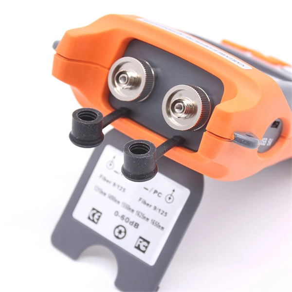
In this Cisco Tech Talk, learn how to view the optical module status on a Cisco switch using the Command Line Interface (CLI). This video demonstrates how to access the optical module status, check for any issues, and monitor the health of your network's optical components. Learn. When optical modules operate on a switch, it is usually necessary to read the module's internal information to understand its working status—such as connection status and real-time metrics like optical power and temperature. Additionally, identifying module information helps detect coding. This chapter describes how to configure the Optical Amplifier Module and Protection Switching Module (PSM). When you plan to replace a configured optical module with a different type of optical module, you must clear the configurations of the old module before you install the new module. By checking module health, compatibility, and digital diagnostics, you can quickly confirm correct installation, detect optical problems, and maintain accurate hardware. Small Form-factor Pluggable modules (SFP module) are the workhorses of modern network connectivity, enabling flexible fiber optic or copper links between switches, routers, firewalls, and servers. Whether you're upgrading bandwidth, replacing a faulty unit, or reconfiguring your topology, knowing.
[PDF]
BARCELONA, Spain, March 6, 2025 /PRNewswire/ -- At the Mobile World Congress 2025 (MWC 2025), Huawei launched the StarryLink optical modules, designed to enhance network experiences with "3S" quality (Spanning, Stable, Secure). This announcement occurred during the data center session titled. Very little is written about Huawei's optical DWDM technology, but that doesn't mean the company hasn't made some big waves in the industry. We had the chance to sit down with the Huawei optical team, led by Gavin Gu, at MWC 2026 to learn about their latest coherent DWDM technology.
[PDF]
Optical trap or "tweezers" is a device used to apply piconewton sized forces and make precise measurements on a scale of roughly one micron. It can be created by applying a precisely focused laser onto a dielectric material. Thorlabs' OTKB (/M) Modular Optical Tweezers provide users with a tool for trapping and manipulating microscopic-sized objects. These laser-based tweezers, or traps, have been employed in numerous biological experiments. Biological applications for optical tweezers include trapping viruses and. Our advanced optical trap generator based on ultra-fast AOD technology. Versatile and flexible optical trap manipulation designed for biological samples. Learn to calibrate the 20. Use calibration information to observe the rotation of E. coli bacteria, and determine the forces required to stop this rotation. Based on their design, Thorlabs has collaborated with the aforementioned authors to design an OTKB optical trapping kit that includes all necessary components and provides the same capabilities. Enclosed into a high-quality aluminum box and assembled onto the. Torr Scientific offers a range of magneto-optical traps (MOT) (also known as atom trap chambers) used as part of ultra-cold vacuum systems, to capture atoms for testing purposes. This is a chamber module, formed of low-magnetic permeability materials for use at ultra-low temperatures nearing.
[PDF]
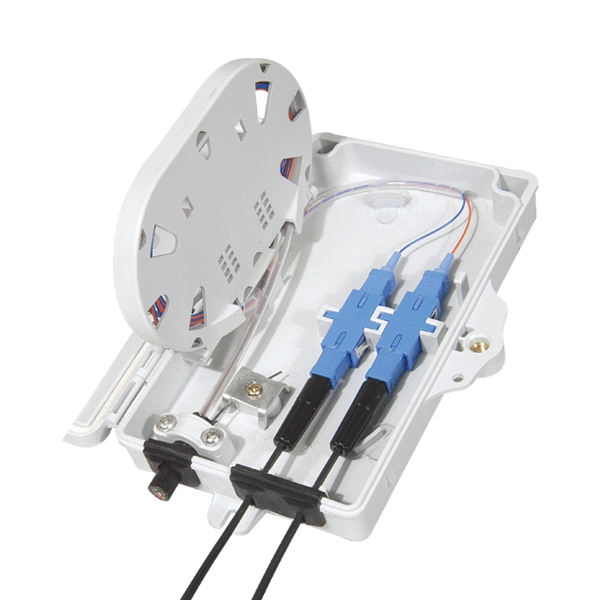
The SFP optical module is a standardized, modular assembly designed to be quickly installed or removed from a device's port without requiring the device to be powered down. This key feature—being hot-pluggable —is essential for simplifying network maintenance and minimizing downtime. SFP (Small Form-factor Pluggable) is a compact, hot-pluggable network interface module used to connect network devices (switches, routers, firewalls) to fiber optic or copper cables. It converts electrical signals into optical (or copper) signals and vice versa. An SFP transceiver acts as a compact, hot-swappable optical transceiver that. An SFP switch uses Small Form-Factor Pluggable (SFP) modules to form a network switch for high-speed connectivity between devices. These interchangeable modules support various media types, including copper or fiber-optic cables, providing flexible networking options based on specific requirements.
[PDF]
The base station can be divided into two modules: the RRU for transmitting signals and the BBU for processing signals. The BBU is small and exquisite, with low power consumption, while the RRU is large and has high power consumption. Which optical modules are commonly used in 4G base stations? In this blog, ETU-LINK will talk about 4G base stations and common types of optical modules. The BBU is small and. In a mobile communication base station, the antenna is at the top of the signal tower, and under the tower is the machine room, in which the base station is placed. Generally, the. RRU and BBU are crucial components in base station construction, enabling a distributed architecture that improves efficiency and reliability. Here's a breakdown of each: The central processing unit in a base station. Handles baseband signal processing, transmission scheduling, and network interfacing. BBU is used for signal processing, RRU is used for signal transmission and reception, and the feeder is used to connect the antenna and the base. The base station is logically divided into two parts: BBU and RRU. RRU is responsible for signal transmission and reception, and BBU is responsible for signal processing. The feeder is used to connect the antenna and the base station, and the supporting equipment is mainly the power supply and air.
[PDF]
The main trade show for the large optical module industry is the Optical Fiber Conference (OFC), that is held annually in southern California. Other prominent shows for the industry include ECOC in Europe and FOE in Japan.
[PDF]
In the field of optical communication, the packaging of optical devices plays a crucial role in the performance and application of optical modules. Common optical device packaging methods include COB (chip-on-board packaging), BOX and coaxial packaging. Today, we will discuss the differences. This article analyzes the requirements of optical transceivers and discusses packaging methods and optical chip types to help readers better understand their design and manufacturing process. They are used in telecom and data communication applications and can be packaged in different ways, including TO, Box, and COB packaging. Regardless of the type of optical module, the. COB packaging means chip-on-board packaging, and the laser chip is adhered to the PCB substrate, which can achieve miniaturization, light weight, high reliability and low cost. The traditional single-channel 10Gb / s or 25Gb / s rate optical module uses SFP package to solder the electrical chip and. The optical transceiver module has three major components, which are opto-electronic devices (TOSA/ROSA), a circuit board with electronic components (PCBA) and optical interfaces (housings) such as LC, SC and MPO. Figure1: Components of an Optical Transceiver The optical transmitting part is.
[PDF]
Optical modules typically have an electrical interface on the side that connects to the inside of the system and an optical interface on the side that connects to the outside world through a fiber optic cable. An optical module is a typically hot-pluggable optical transceiver used in high-bandwidth data communications applications. Composition of Optical Modules The optical module, known as Optical Transceiver in. The optical module serves as a crucial component in optical fiber communication systems, operating at the physical layer, which is the lowest layer in the OSI model. Its primary function is to achieve optoelectronic conversion by converting electrical signals into optical signals and vice versa. Operating at the physical layer of the OSI model, optical modules are core devices in optical.
[PDF]
GPON is an alternative to Ethernet switching in campus networking. GPON replaces the traditional three-tier Ethernet design with a two-tier optic network which eliminates access and distribution Etherne.
[PDF]
OMD-1800 is a bidirectional passive CWDM multiplexer/demultiplexer designed to transmit multiple optical channels over a single fiber. Supporting up to 18 wavelengths, it enables efficient point-to-point fiber utilization while maintaining low insertion loss and high channel. The Model 0201 OMD is a high capacity optical media shredder listed on the NSA/CSS EPL for CD destruction. It is also NSA/CSS EPL listed for DVD destruction through 2024 and meets DIN 66399 Level O-5 standards. The unit produces a residual particle size of 2. This optical. Everything you need to build an optical network from end-to-end. Thin-film filter and PLC based AWG for multiplexing, a full suite of components for optical amplification use, optomechanical or MEMS-based switches for protection or surveillance application, Tap PD for power monitoring and VOA for. The Model 0202 OMD Optical Media Destroyer is a system designed specifically for the destruction of Optical Media (CDs, DVDs). The system has been evaluated by the NSA, meets the NSA/CSS 04-02 Standards and is listed on the NSA Evaluated Products List. By audiobomber January 24 in Buy & Sell Audio and Computer Components This is the latest design and the currently-offered audiophile-grade fiber media converter (FMC), designed for Sonore by John Swenson to isolate network noise. Some erroneously refer to this model as a v3, but there is no v3.
[PDF]