Wavefront shaping enables precise control of light propagation through multimode fibers, facilitating diffraction-limited focusing for applications such as high-resolution single-fiber imaging and high-power fiber amplifiers. While the theoretical intensity enhancement at the focal point is. Light from a high-power laser diode is coupled into a multi-mode fiber (diam:100 um, NA = 0. A de-speckle unit can be turned on and off to reduce any speckles that appear after light leaving the multi-mode fiber. A collimating lens (CL) after the fiber collimates the light to a certain. We present laboratory measurements demonstrating how the output beam profile from multimode fiber can be affected by the beam entry angle. In some applications, an alternative beam distribution such as a top hat or donut is desired instead of the inherent Gaussian distribution provided by typical. Light transport in a highly multimode fiber exhibits complex behavior in space, time, frequency, and polarization, especially in the presence of mode coupling. The newly developed techniques of spatial wavefront shaping turn out to be highly suitable to harness such enormous complexity: a spatial. What are the conditions for efficiently launching light into a multimode fiber? What happens to the intensity profile of light during propagation in a multimode fiber? How do bending and other disturbances affect the output beam profile? What are the challenges of maintaining single-mode.
[PDF]
Long-pass dichroic beam splitters are designed to transmit longer wavelengths of light and reflect shorter wavelengths, while short-pass dichroic beam splitters do the opposite. While this type of beam splitter is less common, it can be useful for fluorescent applications, such as. A beam splitter or beamsplitter is an optical device that splits a beam of light into a transmitted and a reflected beam. It is a crucial part of many optical experimental and measurement systems, such as interferometers, also finding widespread application in fibre optic telecommunications. In its. Beamsplitters are optical components used to split incident light at a designated ratio into two separate beams. Additionally, beamsplitters can be used in reverse to combine two different beams into a single one. Newport offers a wide variety of Beamsplitters in various shapes. a laser beam) into two (or sometimes more) beams, which may or may not have the same optical power (radiant flux). These plates are typically made of high-quality glass coated with a thin, anti-reflective film. The coating helps to minimize issues with annoying back reflections, such.
[PDF]
The AOI impacts the amount of light being reflected and transmitted. For example, most plate beam splitters have an AOI of 45 degrees, which may limit those who need more flexibility. A beam splitter or beamsplitter is an optical device that splits a beam of light into a transmitted and a reflected beam. It is a crucial part of many optical experimental and measurement systems, such as interferometers, also finding widespread application in fibre optic telecommunications. a laser beam) into two (or sometimes more) beams, which may or may not have the same optical power (radiant flux). Their precision and versatility make them indispensable in a variety of scientific, industrial, and technological applications. Beamsplitters are often classified according to their construction: cube or plate. Beamsplitters are fundamental components in optical engineering, serving to precisely divide a single input beam of light into two distinct output beams. This division allows for the simultaneous analysis or utilization of the light's properties along two separate paths. The device is purely. The beam splitter splits and then recombines infrared radiation, while the detector picks up the resulting signal. It's sensitive to both intensity and frequency. Together, they decide just how accurately an instrument captures those unique infrared “fingerprints” from different substances.
[PDF]
Your eyes contain two types of light-sensing cells: rods and cones. Rods detect low-light vision and motion, while cones handle color vision and detail in bright light. Damage to either can lead to vision problems like night blindness or color blindness. Protecting your eyes with proper nutrition. Personnel Safety. Optical Touch Buttons. Self-contained Sensors. Each technology has unique strengths and weaknesses, so the requirements of the application itself will determine what technology should be used. This article is focused on photoelectric sensors and defines what they are, their adv ors are readily present. Quality Control: They can detect defects, ensure proper product placement, and verify the presence of components. Safety: They can be used to create safety barriers, preventing machinery from operating when a person or object is in a hazardous zone. In this section, we explore the geometric optics of the eye. Early thinkers had a wide array of theories regarding vision. Euclid and Ptolemy believed that the eyes emitted rays of light;. Understanding the eye involves examining how its individual parts contribute to the overall function. Vision begins as light enters the eye through the cornea, a transparent, dome-shaped outer.
[PDF]
This comprehensive guide will equip you with the knowledge and steps needed to safely test a lighting circuit using a multimeter. We will cover the essential safety precautions, different testing methods, interpreting the results, and troubleshooting common issues. Understanding the principles. Multimeters are versatile tools used by electricians and hobbyists alike to diagnose electrical problems and ensure the proper function of electrical devices. We'll explain how to measure AC and DC voltage, test for continuity, measure capacitance, measure frequency, and test diodes. Hence the 'multi'-'meter' (multiple measurement) name. The most basic things we measure are voltage. Here is a step-by-step guide on how to test a light fixture with a multimeter for beginners: Step 1: Turn Off the Power Before you begin testing the light fixture, it is crucial to turn off the power to the fixture at the circuit breaker. It's an indispensable tool for troubleshooting and maintaining electrical circuits. Different types of multimeters offer varying degrees of precision and. An easy way to test a light fixture is to remove the bulb and replace it with one that you know is working. If you don't happen to have a working bulb handy, you can use a light socket tester or test the fixture with a multimeter.
[PDF]
Resolving these issues involves steps like checking cable connections, soft resets, updating firmware, and specific solutions for different router brands like ASUS and Spectrum. It often indicates that something is wrong with your internet connection or the device itself. Fortunately, diagnosing and resolving these issues doesn't have to be complicated. In this comprehensive guide, we will walk you through the common causes of a red light on your router and provide. A router showing a red light can mean different things, like a service outage, misconfiguration, or loose connection, all of which can lead to a broken internet connection. Fortunately, there are heaps of ways to fix a red blinking light on your router. One of the first things you should try is to. Turn off the router and disconnect the power cord. Check that the PON cable is free from damage or sprains. Even if you have the best router, you may experience a loss of connection or other issues and see that dreaded red light. When it's green and steady, everything is fine. However, when it blinks red or stays solid red, it signifies a Loss of Signal, a problem preventing your router from communicating.
[PDF]
Los sensores de luz presentan una variedad de dimensiones, desde modelos compactos ideales para aplicaciones domésticas hasta sensores más grandes diseñados para entornos industriales. Estas dim.
[PDF]
It enables uniform, shadow-free lighting by directing light along the same optical axis as the lens. When integrated into specialised lenses, the beam splitter divides the incoming light into two paths: one beam illuminates the object, while the other is used for image capture. Beamsplitters are fundamental components in optical engineering, serving to precisely divide a single input beam of light into two distinct output beams. This division allows for the simultaneous analysis or utilization of the light's properties along two separate paths. Additionally, beamsplitters can be used in reverse to combine two different beams into a single one. In practice, the reflective layer absorbs some light. It is a crucial part of many optical experimental and measurement systems. A cube beam splitter is, at its essence, an optical device that splits an incoming light beam into two sections. What are beamsplitters and how are they used in optics and photonics applications ? Beamsplitters are optical components that are used to. The beam splitter splits and then recombines infrared radiation, while the detector picks up the resulting signal. It's sensitive to both intensity and frequency. Together, they decide just how accurately an instrument captures those unique infrared “fingerprints” from different substances.
[PDF]
Check the electrical load and ensure that the sensors do not exceed the 10 Amp maximum. Check each wire for damage that may lead to a short. Check the following: Check if all cable connections are tightened with a torque moment of 14Nm (17Nm for the M10 model). Check if the surface area. Channel has NO voltage and there is an active fault. Check for tripped or missing circuit breaker Sticky fault on the channel. Sticky Fault - an indicator that a fault has occurred that will stay until the indicator has been cleared manually. Channel has NO. Each powernet distribution box (PNDB) on the vehicle provides up to 4 low amperage circuits (30 amp and less), and up to three high amperage circuits through midi fuses. The fuses are located behind a cover on the face of the PNDB. On vehicles equipped with a cab load disconnect switch (CLDS), the. I have the following issues, green light on shunt all red lights on distributor, no SOC on screen. Everything else is working great. In troubleshooting I removed all the fuses from the distributor just to see if the fuse lights would not illuminate red and get green power. Any. Show the control box indicator lights. Show the accessory response (or lack of response). For LED Light Kit issues, also provide a photo of the LED Y-cable (to confirm which version you have). Videos and photos are required to file warranty claims with the manufacturer.
[PDF]
If the LOS light on your fiber router or ONT is blinking red, it usually means Loss Of Signal. This guide explains the likely causes, the checks you can do at home, and when the issue needs technician support. The LOS light on your router indicates the status of your internet connection to the Internet Service Provider (ISP). When it's green and steady, everything is fine. However, when it blinks red or stays solid red, it signifies a Loss of Signal, a problem preventing your router from communicating. That blinking red LOS light means your router has lost its connection to your internet provider's network. Before you panic or call tech support, there are several simple fixes you can try at home that often solve this problem in minutes. In most cases, a loss of signal indicates a technical issue with the. The tables in this article provide detailed information about the possible appearances of the LED lights on each device, the possible causes of each state, and what you should do. Ensure your Fiber Jack is connected to the network and the LED lights are connected and working properly before moving. Red light means LOS (Loss of Signal) on your fiber connection. Need to reach out to your ISP and have them diagnose signal loss Did you try turning it off and on again? Good old INACT ONT alarm. Thanks! LOS aka loss of signal indicates a line side issue occurring where the.
[PDF]
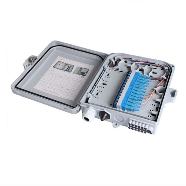
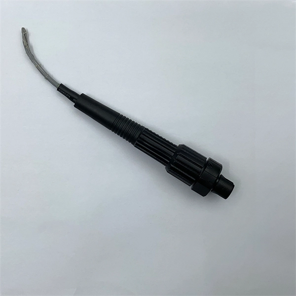
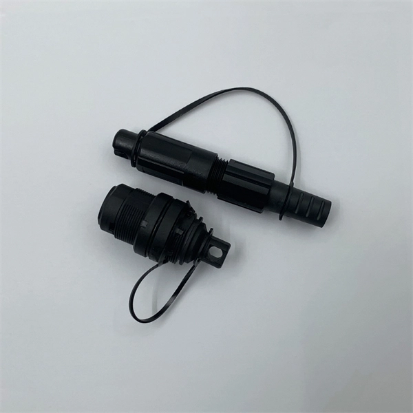
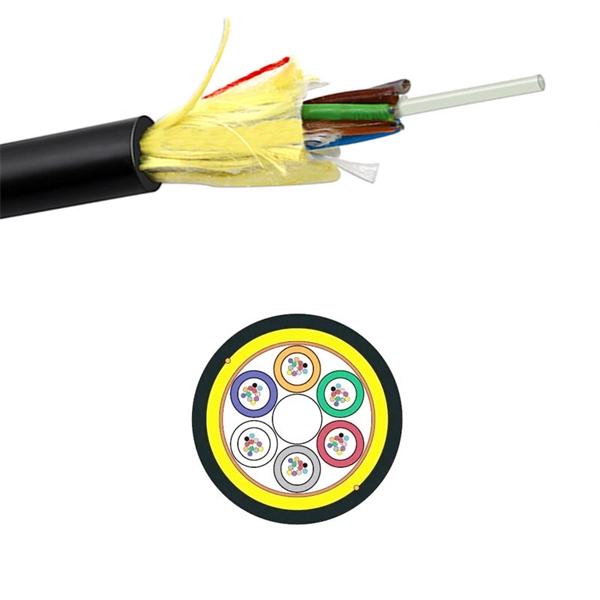
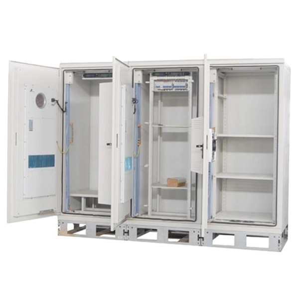
Through the adapter in the distribution box, the optical signal is led out by the optical jumper to realize the optical wiring function. An optical cable consists of three primary parts: the core, the cladding, and the protective sheath. The core is at the center of the optical cable and serves as the pathway for transmitting light signals. Surrounding the core is the cladding, which has a lower refractive index than the core. In the complex architecture of fiber optic networks, the Optical Distribution Frame (ODF) serves as the linchpin for organizing, protecting, and distributing optical signals. Whether in data centers, telecom central offices, or enterprise network rooms, ODFs enable efficient fiber management. The optical fiber distribution box is to protect the connection point where the optical cable is connected to the user end, so that the optical cable access point is stable, dustproof and waterproof. What is a fiber distribution box? 2. The. A fiber distribution box (FDB) functions as a central hub in fiber optic networks where the main cable is split into multiple individual fibers for distribution to end users. These boxes protect sensitive fiber connections from environmental factors while providing an organized framework for.
[PDF]
Singlemode fiber features a small core diameter of just 9 µm and allows only one mode of light to propagate. This design minimizes signal loss and supports high-bandwidth applications over long distances. 5 µm) with multiple light. Single-mode fibers (also called monomode fibers) are optical fibers which are designed such that they support only a single propagation mode (LP 01) per polarization direction for a given wavelength. Higher-order modes like LP 11, LP 20 etc. It allows just one light signal – typically lasers – to pass through at a time. This keeps the signal tight and strong, making it ideal for long. Optical Fiber comes in two main categories: singlemode and multimode. Singlemode fiber is designed for long-distance data transmission, typically over distances greater than 10 kilometers. Glass or plastic are often used to make these fibers. Metal wires are used in optical fibers because they protect against damage and are immune to electromagnetic interference. This characteristic allows for significantly less signal degradation and higher data rates over.
[PDF]
This video shows 2D wave simulations of optical fibers and presents differences between single-mode and multi-mode light propagation. more Audio tracks for some languages were automatically generated. Learn more. This applet is called FIMOC (fiber-optic mode online calculator). With it you will be able to calculate and visualize the propagating modes of any step-index fiber of your choice. If you want to go directly to the software, scroll to the bottom, but if you are interested in where these modes come. Optical fiber sensors have attracted significant interest in the sensing field. This paper presents a C-shaped optical fiber sensor sensitivity enhancement through design. RP Fiber Power is a powerful software for simulation, design and optimization of fiber devices — in particular, fiber amplifiers and lasers as well as other types of waveguide lasers (and even many bulk lasers), but also fiber couplers, multi-core fibers, helical core fibers, tapered fibers and. In this proposed workflow, we couple Ansys Mechanical TM with Ansys Lumerical TM, creating an innovative workflow that can detect the position of a random mechanical strain along an optical fiber. In this proposed workflow, DFOS utilizes standard single mode optical fiber as a sensing element. 1Department of Mechanical and Aerospace Engineering, University of Texas at Arlington, 500 W.
[PDF]
This section provides a list of the top 10 Spectrometer manufacturers, Website links, company profile, locations is provided for each company. Here are the top-ranked spectroscopic analyzer companies as of May, 2026: 1. Spectral Products, 3. International Light Technologies, Inc. What Is Spectroscopic Analyzer?. Explore the spectrometers market's most influential companies driving innovation, competitive performance, and industry trends in 2025–2030. Discover how each leader is shaping chemical analysis, environmental monitoring, life sciences, and more — with holistic insights available in the detailed. Based on our evaluations of 807 Spectrometry and the analysis of over 730 consumer satisfaction reviews, We have rank top 29 Best Spectrometry reviews of different brands, such as EISCO, vinmax, CGOLDENWALL, Hach Company, X-Rite, Fencia, zorvo, genmine, 3B Scientific, M&A INSTRUMENTS INC, YFYIQI. SPECTRO is a leading provider of spectrometers, offering a range of solutions including handheld models for metal recycling and advanced systems for automated sample preparation and analysis. Their expertise in optical emission and X-ray fluorescence spectrometry positions them as a key player in. With the numerous uses, spectrophotometer manufacturers are innovating spectrophotometers per clients' needs. A spectrophotometer measures the quantity of light that can pass through a sample.
[PDF]
This document provides the users of USB4000 Spectrometers with instructions for setting up, calibrating and performing experiments with their spectrometer. Remote fiber optic spectroscopy is a sophisticated technique that uses fiber optic couplers, cables, and accessories to analyze samples at a distance from the spectrophotometer. The technique unlocks a range of experiments that standard UV-Vis or fluorescence instruments cannot accommodate. The. Fiber optic spectrometers have revolutionized the field of remote sensing and data acquisition, providing unprecedented flexibility and precision. These devices utilize the unique properties of fiber optics to measure and analyze the spectral composition of light, making them indispensable tools in. The Cary 60 Fiber Optic Coupler and the Cary 60 Dip Probe Coupler are optional accessories for the Cary 60 UV-Vis spectrophotometer. Both accessories convert the Cary 60 UV-Vis into a remote fiber optic measurement system. Contains descriptive. Near-Infrared Spectroscopy (NIR) offers important advantages in analytical chemistry, particularly in process monitoring and quality control across various industries. This paper details the operational principles, methodologies, and significant advancements in NIR spectroscopy, emphasizing the. The basics of fiber optic cables and bundles and how they can be used to collect and direct light are discussed in 'An Introduction to a Spectrometer: Fiber Optic Bundles'.
[PDF]