Bangladesh Digital Spectrum Analyzer Suppliers Directory provides list of Bangladesh Digital Spectrum Analyzer Suppliers & Exporters who wanted to export digital spectrum analyzer from Bangladesh. Don't know your target market? Wanted to market your. UTS1000 series handheld spectrum analyzer is designed for field use. It is light in weight, with simple structure, rich measurement function, and it is the best choice for excellent performance and value. It is equipped with high-brightness 6. 5-inch widescreen LCD display, dynamic appearance, and. The Bangladesh Spectrum Analyzer Market is likely to experience consistent growth rate gains over the period 2025 to 2029. 29% in 2025, growth builds up to 0. 34%, as part of. Buy official Hantek products best price in Bangladesh from ZerOne Tech. Authorized supplier of Hantek. Buy a new original hantek product Oscilloscope,Function generator,Power Supply. Fast delivery & genuine products. Features · Frequency range: 9KHz-3. 2GHz (tunable to 9KHz) AC Coupled · Optimal. The JC3030 is a high-performance visual spectrum audio analyzer designed for music lovers, home theater enthusiasts, streamers, and studio setups. Featuring an integrated signal generator and an intuitive 2. bd Wide Variety of spectrum display analyzer. Great Prices, Even Better Service.
[PDF]
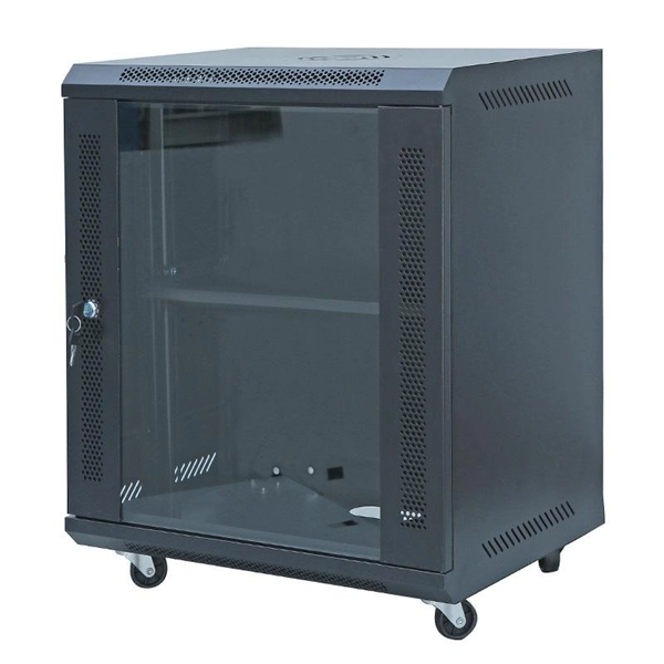
Home distribution boxes typically handle single-phase power supplies and contain 6 to 24 circuits. They include standard circuit breakers for lighting, outlets, and major appliances like water heaters and air conditioning units. You lower the chance of circuits getting too hot or overloaded when you pick the right box for your needs. You leave space for safety devices like circuit breakers and surge protectors. A distribution box, also known as a distribution board, electrical panel, or breaker box, is an enclosure that houses electrical components responsible for distributing electricity throughout a building. It receives power from the main electrical supply and divides it into separate circuits, each. Your circuit count leads directly to the box size. Most homes need: Future-Proofing: Add 20% extra circuit spaces upfront. Future solar panels or EV chargers won't require expensive upgrades. Its primary roles are distribution, protection (using devices like. Residential Settings: For homes, a distribution box should manage basic circuits for lighting, outlets, and common appliances. A smaller, compact box with standard circuit breakers is typically sufficient for household needs, where power demand is relatively low. Whether you're upgrading your home's electrical service, designing a commercial facility, or managing an industrial power system, selecting and sizing the right.
[PDF]
Pick the right size distribution box to keep things safe. This stops too much power and keeps wires from getting too hot. It also lets you add more stuff later if needed. Use electrical diagrams to see where circuits go. Diagrams are like maps for your wires. They help you. A neat, well-organized service panel or subpanel is easier and safer to work in; it will also be an easier panel in which to add circuits later on. A neat, well-organized subpanel bundles wires to conserve space and improve access. Ideally, wire groups are installed in layers and wires are bent at. In this video, we'll walk you through the process of wiring a home distribution box with a detailed connection diagram. It serves as a central hub for distributing electricity throughout a building, ensuring that power is delivered safely and efficiently to all the required locations. A distribution box is the heart of any electrical system. Whether in a home or an industrial facility, this box keeps your electrical setup organized, functional, and efficient. Material preparation: Prepare the required circuit breakers, wires, wiring ties and other materials, and ensure that they meet the design drawings and installation requirements. Location determination:. A single phase breaker box, also known as a distribution board, is an electrical panel that controls and distributes electrical power in residential and commercial buildings. The wiring diagram.
[PDF]
By breaking power into smaller, manageable loads, the box ensures consistent delivery while protecting each circuit from overload. Inside, it houses circuit breakers, busbars, and terminals that collectively control and protect electrical flow. Correct wiring methods for circuit breakers within distribution boxes are fundamental to ensuring electrical safety and compliance with established codes. The distinction between 1P and 2P circuit breakers plays a pivotal role in determining the appropriate protection level for various circuits. What is the distribution box? A. A distribution board (DB) is the central component of any power distribution system, providing a safe and organized way to deliver electricity from the main supply to individual circuits. Understanding its significance. A distribution box is a vital piece of equipment that ensures the effective and safe distribution of electrical power in various parts within a building or complex. It is widely employed in residential, commercial and industrial set-ups for circuit control and protection. By knowing their great.
[PDF]
There are many types of protective relays, and each one is designed for a specific type of protection. Common types include overcurrent relay, differential relay, distance relay, earth fault relay, and under/over voltage relay. Protective Relay Definition: A protective relay is an automatic device that senses abnormal conditions in electrical circuits and triggers actions to isolate faults. Types of Protective Relays: Protective relays are categorized by their mechanism (electromagnetic, static, mechanical) and function. This article covers various types of protective relays, such as overcurrent, directional, and differential relays, highlighting their operating characteristics and applications in electrical systems. Its main purpose is to safeguard electrical equipment like transformers, generators, and transmission lines from damage due to. Understanding the different types of protective relays and the applications of differential relays is crucial for anyone involved in electrical engineering or maintenance. The selection of relay depends on the type of equipment and fault. The rectangular devices are test connection blocks, used for testing and isolation of instrument transformer circuits. : 4 The first protective relays were electromagnetic.
[PDF]
In EMC testing, a spectrum analyzer is used for basic precompliance testing; however, it can not be used for full testing and certification. Instead, an EMI receiver is used.OverviewA spectrum analyzer measures the magnitude of an input signal versus frequency within the full frequency range of the instrument. The primary use is to measure the power of the spectrum of known and. analysis was first used by in the late 1600s. In a letter to the, he described how he used an optical prism to separate white light into its constituent colors. Spectrum a. Spectrum analyzer types are distinguished by the methods used to obtain the spectrum of a signal. There are swept-tuned and fast Fourier transform (FFT) based spectrum analyzers: • A.
[PDF]
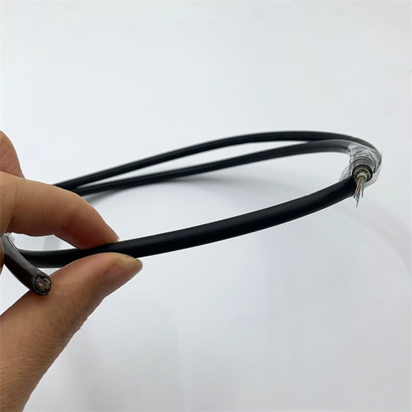
This application note explains how Site Master is used to measure cable insertion loss with different test methods and how to predict the maximum allowable cable insertion loss through manual calculations. Desktop Insertion Return Loss Tester with color screen has stable and reliable performance, which integrates stable light source, high-precision power meter, insertion loss meter and return loss meter into one multifunction instrument. Based on domestic customers'. Modern handheld analyzers, like the Keysight FieldFox Analysers, are designed specifically for cable and antenna testing (CAT), offering fast and accurate insertion loss testing across a wide frequency range. These tools are invaluable for both installation and maintenance, enabling field. Insertion loss is expressed in decibels or dB. The decibel is a logarithmic expression of the ratio of output voltage (voltage of the signal received at the end of the link) divided by input voltage (the voltage launched into the cable by the transmitter). 0 PCB transmission line losses in a PCB production environment. In wireless communication systems, the transmit and receive antennas are connected to the.
[PDF]
This document describes how to use and program the Photonic Application Suite, Insertion Loss Engine. Insertion loss is measured by comparing signal power (or sound level) before and after it passes through a component or system, then expressing the difference in decibels (dB). The core process is the same across fiber optics, RF electronics, and acoustics: establish a baseline reference without. This tutorial aims to help RF engineers understand how to test and measure various RF specifications of RF power amplifiers, RF LNAs (Low-Noise Amplifiers), and RF transceivers using RF test and measurement equipment like spectrum analyzers, signal generators, and sweep oscillators. Gain is the. Coaxial cables are essential components in transmitting radio frequency (RF) signals, but they inherently attenuate these signals, a phenomenon known as cable loss or insertion loss. Yes, I would like to receive educational or promotional emails from Keysight. By clicking the button, you. Insertion loss is a critical parameter in RF engineering that refers to the loss of signal power that occurs when a component or device is inserted into a transmission line or circuit. The insertion loss measurement quantifies the effect of the resistance the cabling link offers to the transmission of the electrical signals. Insertion loss characteristics of a.
[PDF]