A common test setup to evaluate Stressed Receiver Sensitivity involves measuring the Optical Modulation Amplitude (OMA) using a square wave, per the standard guidelines. Receiver sensitivity stands as a critical parameter impacting an optical transceiver's functionality. It denotes a module's capability to function in challenging environments and aids network operators in determining the system's maximum reach or link margin. These metrics provide insights into how well your transceivers perform under different conditions, ensuring seamless data transmission. Optical. Whether you're a network engineer validating new inventory or an integrator preparing for deployment, knowing how to test optical transceiver modules can save time, reduce failures, and ensure SLA compliance. Unchecked optical modules can cause: Testing ensures compliance with IEEE 802. 3 and MSA. In optical communication systems, sensitivity is a measure of how weak an input signal can get before the bit-error ratio (BER) exceeds some specified number. The standards body governing the application sets this specified BER. For example, SONET specifies that the BER must be 10 -10 or better. Why Fiber Optic Transceiver Testing is Important? Identify faults and failures: Transceiver testing helps in identifying any faults.
[PDF]
5D optical data storage is an experimental nanostructured glass for permanently recording digital data using a femtosecond laser writing process. It is also branded Superman memory crystal, in reference to the Kryptonian memory crystals from the Superman franchise. Discs using this technology could be capable of storing up to 360 terabytes worth of data (at the largest size, 12 cm. Technical designThe concept is to store data optically in non- transparent materials such as, which has high chemical stability. Recording data using a was first proposed and demonstrat. In 2018, Professor Peter Kazansky used the technology to store a copy of 's, which was launched into space aboard in association with the.
[PDF]
As illustrated in typical SFP internal structure diagrams, the module's core components include an optical transmitter assembly (TOSA), laser driver, optical receiver assembly (ROSA)—some high-sensitivity modules (like L16. 2) use APD receivers, which require an additional booster. As a key element in optical communication systems, optical transceivers serve as media between network devices to transmit and receive data. There has been lots of articles and guides on transceiver modules in the perspective of the package type while only a few of them cover the internal elements. Optical modules are devices used to connect network devices, transmit and receive data between network devices, and can be used to convert optical and electrical signals. The optical module is a very important component in an optical communication system. When you remove the metal housing of the optical transceiver, you will find that the internal components are connected to each other. The following section will focus on. In the era of 5G, AI, and high-speed data centers, optical modules serve as the core bridge for converting electrical signals to optical signals (and vice versa), enabling fast, reliable data transmission across networks. Among various optical module form factors, SFP (Small Form-Factor Pluggable). The optical transceiver module is mainly composed of three parts: housing, optical device and integrated circuit board. The following section will focus on.
[PDF]
The Optical Module Chip Base is a critical packaging platform designed to support core components such as laser chips, detector chips, and driver chips in high-speed optical communication modules. The primary optical communication devices used are optical modules and optical chips, which are essential for high-speed data transfer and network interconnection. It serves as a bridge between the chip and external optical fibers or circuit systems, ensuring. In the backbone of the global digital infrastructure, optical modules are the unsung heroes, converting electrical signals into pulses of light and back again, enabling the high-speed data transmission that powers the internet, cloud computing, and telecommunications. At the heart of every advanced. An optical module is a device that converts electrical signals into optical signals and vice versa. Among various optical module form factors, SFP (Small Form-Factor Pluggable).
[PDF]
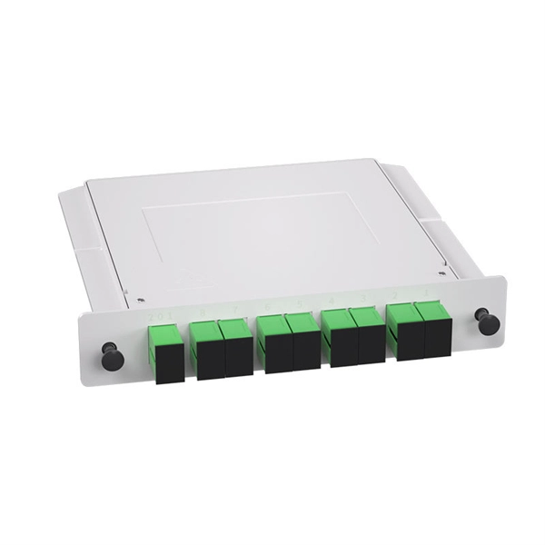
This market research report provides a comprehensive analysis of the current size of the Optical Modules industry. It leverages historical data to extract key industry insights, tracing the market's evolution over time. Optical Module Package Market was valued at 8942 million in 2024 and is projected to reach US$ 20220 million by 2032, at a CAGR of 12. Quotas are established by legislation, Presidential Proclamations or Executive Orders. Quotas are announced in specific legislation or may be provided for. Segments - by Product Type (Transceivers, Cables, Amplifiers, Splitters, and Others), Application (Data Centers, Telecommunications, Enterprises, and Others), Data Rate (10G, 25G, 40G, 100G, 400G, and Others), Form Factor (SFP, QSFP, CFP, and Others), and Region (Asia Pacific, North America, Latin. The global market for Optical Modules was estimated to be worth US$ 17590 million in 2024 and is forecast to a readjusted size of US$ 56786 million by 2031 with a CAGR of 15. 8% during the forecast period 2025-2031. The potential shifts in the 2025 U. QSFP-DD (Quad Small Form-factor Pluggable-Double Density) Optical Module: Double-density four-channel small pluggable packaged optical.
[PDF]
Check the diagnostic information, which shows that the received optical power is low, with a threshold of -3 to -23. 01, currently at -22. Once it exceeds the threshold, an alarm will be triggered. Troubleshoot the link, and if the link is normal, replace the optical. Run the display interface transceiver verbose command in the user view to check whether the transmit optical power (Tx Power) of the interface is within the allowed range. If yes, collect alarm, log, and configuration information, and contact technical support personnel. If the optical module is. An optical module was faulty. Cause 2: Output Optical Power Too High. Services on the optical module may be affected, which may cause bit errors, error packets, or even service interruption. During use, reading optical module information helps understand its real-time operating status, enabling faster troubleshooting of link abnormalities. The following uses the. The International Photonics & Electronics Committee (IPEC) is an international standards organization that is committed to developing open optoelectronic standards and delivering strategic roadmap reports. IPEC focuses on standardizing solutions in optical chips, optical/electrical components, and. The optical module on the port generates an alarm. Often referred as I²C, I2C, IIC (Inter-Integrated Circuit), MDIO (Management Data Input/Output) or CMIS (Common Management Interface Specification), these serial bus.
[PDF]
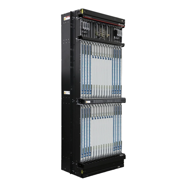
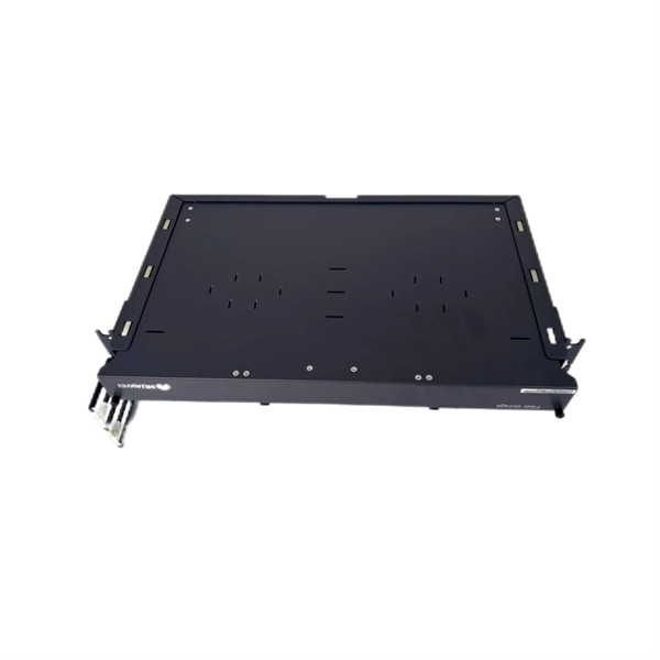
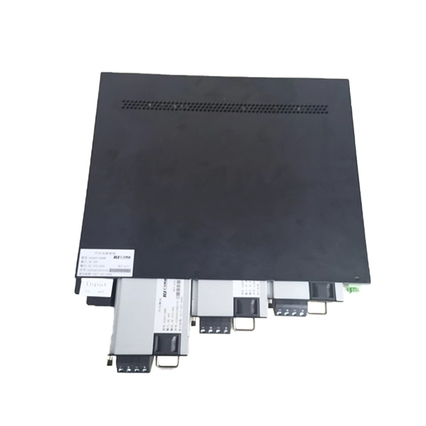
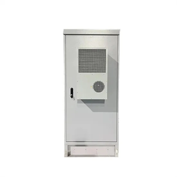
Delta's modular datacenter solution offers a datacenter environment that provides safe equipment operations within the racks, and supports the development and standardizing of micro datacenters that fit into racks. Delta InfraSuite is a new generation, highly integrated modular datacenter solution. It uses racks as the datacenter carrier and fully integrates all sub-systems including UPSs, cooling, power distribution, lightning protection, fire control (optional), wiring, airflow management, intelligent. Rack-Level, 3. 5kW Edge Infrastructure with Integrated Backup Cooling for Remote and Space-Constrained Environments What Makes a Micro Data Center the Ideal Solution? A micro data center is a compact, self-contained infrastructure solution that integrates compute resources, storage, power. Delta InfraSuite is a new generation, highly integrated modular datacenter solution. Its mission statement, “To provide innovative, clean and energy-efficient solutions for a better tomorrow,” focuses on addressing key environmental ssues such as global climate change. As an energy-saving solutions provider with core competencies in power.
[PDF]
BARCELONA, Spain, March 6, 2025 /PRNewswire/ -- At the Mobile World Congress 2025 (MWC 2025), Huawei launched the StarryLink optical modules, designed to enhance network experiences with "3S" quality (Spanning, Stable, Secure). This announcement occurred during the data center session titled. Very little is written about Huawei's optical DWDM technology, but that doesn't mean the company hasn't made some big waves in the industry. We had the chance to sit down with the Huawei optical team, led by Gavin Gu, at MWC 2026 to learn about their latest coherent DWDM technology.
[PDF]
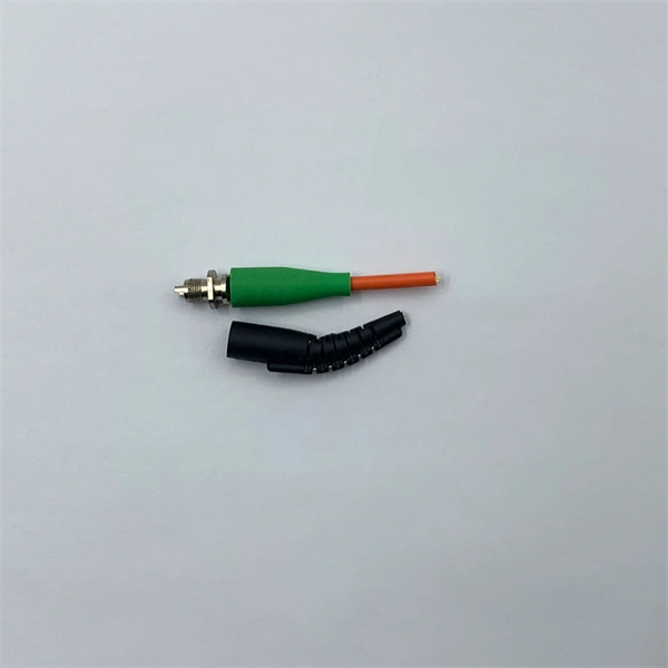
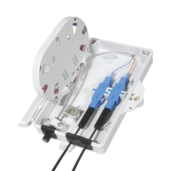
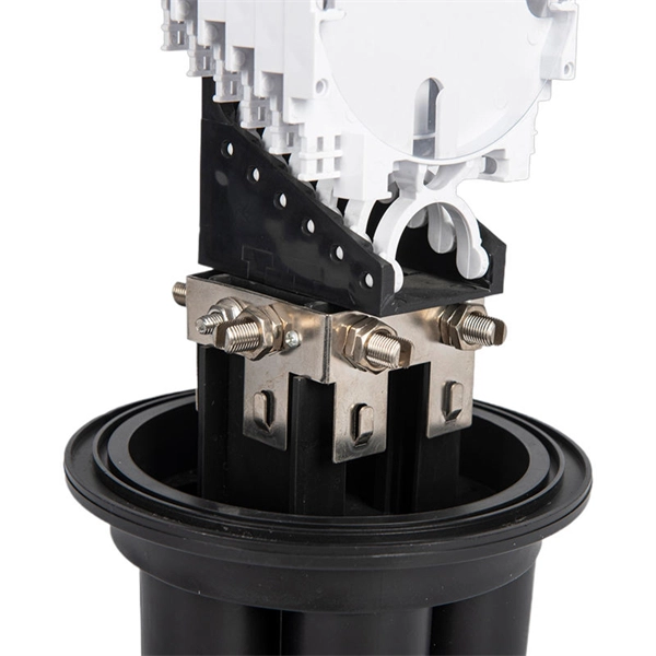
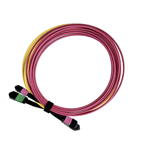
This step-by-step guide aims to provide a comprehensive understanding of the techniques and considerations involved in successfully connecting optical fibers, offering invaluable insights for professionals and enthusiasts in the field. In high-speed data networks, the seamless integration of fiber optic cables with SFP (Small Form-Factor Pluggable) modules is critical for reliable signal transmission. SFP transceivers bridge electrical and optical signals, making them indispensable in data centers, telecom networks, and. Proper connection of fiber optic cables is essential to harness these benefits fully, as even minor errors can lead to significant performance issues like signal loss. This article will guide you through the necessary tools, materials, and methods on how to connect fiber optic cables effectively. This section describes how to install optical transceivers on the SFP or SFP+ ports and connect them to the ports of the peer device using optical fibers according to the network plan. The USG supports both 1 Gbit/s, 10 Gbit/s, and 40 Gbit/s optical modules. The optical modules at both ends are. There are many types of fiber optic connectors, including SC, LC, FC, ST, D4, MU, MT/MPO, etc. These connectors can be divided into single-mode and multi-mode fiber optic connectors according to their structure and purpose. In this tutorial.
[PDF]
The CFP standard defines a pluggable optical transceiver form factor capable of supporting 40G and 100G Ethernet, OTN (Optical Transport Network), and SONET/SDH protocols. The acronym "CFP" represents the Roman numeral "C" (100), aligning it with 100 Gigabit Ethernet. Originally introduced as the first standardized pluggable solution for 100 Gigabit Ethernet, CFP (C Form-factor Pluggable) modules were engineered to support high-bandwidth, long-distance transmission using multiple optical lanes. Their robust design made them ideal for carrier-grade networks, DWDM. The C form-factor pluggable (CFP, 100G form factor pluggable, where C is Latin: centum "hundred") is a multi-source agreement to produce a common form-factor for the transmission of high-speed digital signals. Developed collaboratively. The CFP optical transceiver module is a standardized, hot-swappable optical transceiver used for high-speed data transmission in telecommunications and data center networks. CFP transceivers are defined by CFP MSA to enable 40 Gb/s, 100 Gb/s and 400 Gb/s applications. It features a new concept known as. This article breaks down the key differences between CFP, CFP2, CFP4, and CFP8 optical transceivers commonly used in fiber optic networks. Figure 1: Dimensions of CFP, CFP2, CFP4, and CFP8 The table below summarizes the specifications of each form factor: 24 W (Max. ) In essence, the progression.
[PDF]
SFP28 (Small Form-Factor Pluggable 28) is an enhanced version of SFP+, designed to support 25Gb/s data rate transmission while maintaining the same package type. SFP28 is backward compatible with SFP+. However, compatibility can vary based on the specific SFP models, networking equipment, and vendors involved. It's advisable to consult your vendor for precise information regarding compatibility. ①. This article helps network engineers and field techs confirm SFP backward compatibility when mixing SFP, SFP+, and SFP28 optics in the same switching ecosystem. You will get concrete specs, a decision checklist, and troubleshooting patterns that show up in daily operations. ① Plug a 1000BASE-SX SFP transceiver into the SFP port on a gigabit. Common form factors are SFP (1 G), SFP+ (10 G), SFP28 (25 G), QSFP+ (40 G) and QSFP28 (100 G). The question we answer below is simple: “Which of these can I mix and match without killing the link? What “compatibility” really means? All reputable transceivers follow the Multi-Source Agreement (MSA). SFP28 optical transceiver modules provide a transmission rate of 25 Gbps and use LC connectors. 25G SR/eSR are not supported for use. Q: Can I use an SFP transceiver in SFP28 ports? A: Yes, you can. However, it's important to note that while SFP transceivers and cables can be plugged into SFP28 ports, they won't support the higher 25Gb/s data rate of the SFP28.
[PDF]
An optical module is a typically hot-pluggable optical transceiver used in high-bandwidth data communications applications. Optical modules typically have an electrical interface on the side that connects to the inside of the system and an optical interface on the side that connects to the outside world through a fiber optic cable. The form factor and electrical interface are often specified by an int. Electrical Interface TypesThere have been multiple variants of the electrical interface of optical modules that have been used over the years. The earliest forms of optical modules had an analog electrical interface. In the transmit dir. Many different forms of optical modulation and multiplexing have been employed in optical modules. The most common modulation technique historically has been or NRZ.
[PDF]
The main trade show for the large optical module industry is the Optical Fiber Conference (OFC), that is held annually in southern California. Other prominent shows for the industry include ECOC in Europe and FOE in Japan.
[PDF]
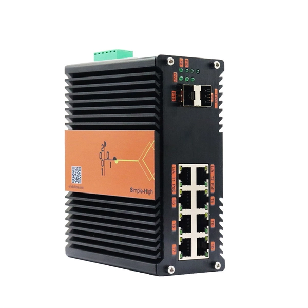
The base station can be divided into two modules: the RRU for transmitting signals and the BBU for processing signals. The BBU is small and exquisite, with low power consumption, while the RRU is large and has high power consumption. Which optical modules are commonly used in 4G base stations? In this blog, ETU-LINK will talk about 4G base stations and common types of optical modules. The BBU is small and. In a mobile communication base station, the antenna is at the top of the signal tower, and under the tower is the machine room, in which the base station is placed. Generally, the. RRU and BBU are crucial components in base station construction, enabling a distributed architecture that improves efficiency and reliability. Here's a breakdown of each: The central processing unit in a base station. Handles baseband signal processing, transmission scheduling, and network interfacing. BBU is used for signal processing, RRU is used for signal transmission and reception, and the feeder is used to connect the antenna and the base. The base station is logically divided into two parts: BBU and RRU. RRU is responsible for signal transmission and reception, and BBU is responsible for signal processing. The feeder is used to connect the antenna and the base station, and the supporting equipment is mainly the power supply and air.
[PDF]
Optical modules typically have an electrical interface on the side that connects to the inside of the system and an optical interface on the side that connects to the outside world through a fiber optic cable. An optical module is a typically hot-pluggable optical transceiver used in high-bandwidth data communications applications. Composition of Optical Modules The optical module, known as Optical Transceiver in. The optical module serves as a crucial component in optical fiber communication systems, operating at the physical layer, which is the lowest layer in the OSI model. Its primary function is to achieve optoelectronic conversion by converting electrical signals into optical signals and vice versa. Operating at the physical layer of the OSI model, optical modules are core devices in optical.
[PDF]