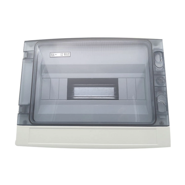
This video shows real on-site footage of electrical installation, demonstrating safe and standardized wiring methods used by professionals. more Learn how to wire a distribution box step by step!. A distribution box, also known as an electrical distribution board, is a critical component in electrical systems. It serves as a central point for distributing electricity to various circuits in a building or facility. It has three categories: residential, commercial and industrial electrical distribution boxes, all of which play important roles in their respective electrical. In modern electrical systems, cable distribution boxes (also known as electrical distribution boxes or distribution boxes) play a crucial role as the key hub for managing, distributing, and protecting circuits. What is the role of the electrical panel? It's also called the breaker box or distribution board. It's the central hub that divides main service lines into smaller branch.
[PDF]
The primary function of a feeder wire is to facilitate bulk power transfer from a central source to a subpanel or a secondary distribution center. An example is the large cable running from the main service panel to a subpanel in a detached garage, basement, or workshop. A main panel and a sub-panel are both important components of an electrical distribution system. It is usually located where the main electrical service enters the building, often on an. Main feeder wires are the arteries of a building's electrical system, designed to safely and efficiently transport a large volume of power from the service entrance to secondary distribution points. They form the backbone of the electrical distribution network, handling the substantial current. An electrical sub panel, also known as a sub distribution board or sub circuit breaker panel, is a smaller secondary panel connected to the main electrical panel in a building. It serves as an extension of the main electrical panel to distribute power to different areas or circuits within a. Distribution board is a safe system designed for house or building that included protective devices, isolator switches, circuit breaker and fuses to safely connect the cables and wires to the sub circuits and final sub circuits including their associated Live (Phase) Neutral and Earth conductors. The distribution box acts as the center of power distribution, distributing electricity to all connected devices.
[PDF]
This video shows real on-site footage of electrical installation, demonstrating safe and standardized wiring methods used by professionals. more Learn how to wire a distribution box step by step! This video shows real on-site footage of. Hey, in this article we are going to see the Single Phase Distribution Box Wiring Diagram and Connection Procedure. A distribution board or distribution box is where the main power supply is distributed to multiple loads. And all the switching and protective devices are installed in the. Box installation: Make sure that Distribution box has been correctly installed and fixed. Material preparation: Prepare the required circuit breakers, wires, wiring ties and other materials, and ensure that they meet the design drawings and installation requirements. Location determination:. In this video, we'll walk you through the process of wiring a home distribution box with a detailed connection diagram. Whether you're an electrician or a DIY enthusiast, this guide will help you understand the basics of home electrical distribution. What Is a Distribution Box? A distribution box, also known as an electrical distribution board, is a critical component in electrical systems. It serves as a.
[PDF]
In this video, we'll walk you through the process of wiring a home distribution box with a detailed connection diagram. Whether you're an electrician or a DIY enthusiast, this guide will help you understand the basics of home electrical distribution. more Welcome to our channel! In this video. A distribution box is the heart of any electrical system. It takes the incoming power and safely distributes it to different circuits throughout your building. However, the key to. In this article, we'll explain how to install a weatherproof electrical box, from selecting the right materials to properly securing the box in place. Weatherproof electrical boxes are designed to handle extreme weather conditions, such as heavy rain and strong winds. They're also designed to. Whether you're a do-it-yourselfer, the neighborhood handyman, or a professional electrician, knowing how to properly install a weatherproof electrical junction box can save time, and your system components will continueto operate for years. Standard indoor electrical boxes are not designed to handle exposure to rain, snow, or high humidity, which can quickly lead to corrosion. Whether adding a GFCI outlet for safety or upgrading an exterior outlet for weather-resistant durability, it's essential to follow proper electrical wiring guidelines to ensure compliance with local codes and prevent hazards. This guide explains the different types of outdoor electrical boxes.
[PDF]
It can also describe a unit that is 1U high and half the depth of a 4-post rack (such as a network switch, router, KVM switch, or server), such that two units can be mounted in 1U of space (one mounted at the front of the rack and one at the rear).OverviewA rack unit (abbreviated U or RU) is a unit of measure defined as 1+3⁄4 inches (44.45 mm). It is most frequently used as a measurement of the overall height of, as well as the height of eq. The rack unit size is based on a standard rack specification as defined in -310. The specifies a standard rack unit as the unit of height; it also defines a similar unit, (HP), used to measure the width o. A typical full-size rack is 42U, which means it holds just over 6 feet (180 cm) of equipment, and a typical "half-height" rack is 18U–22U, which is around 3 feet (91 cm) high. The mounti.
[PDF]
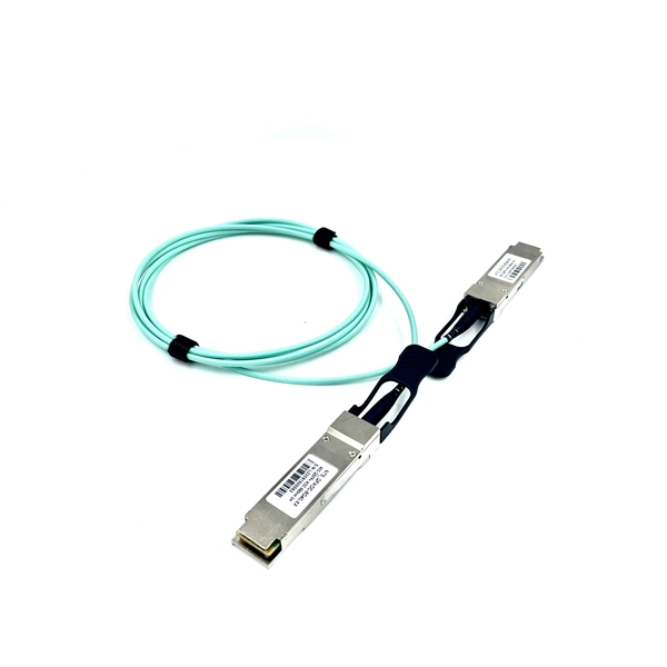
Shop DigiKey's large in-stock selection of Fiber Optic Attenuators. View inventory, pricing and order now for same day shipping!. Optical attenuators are devices designed to reduce the optical power of a light beam or signal by a specific ratio (attenuation factor), typically expressed in decibels (dB). Unlike simple beam blockers or shutters, attenuators are intended to maintain the temporal waveform and usually the mode. FS fixed and variable fiber optic attenuators with leading attenuating fibers guarantee consistent and stable fiber attenuation (0~60dB) in WDM transmission. Basic types of fixed attenuation include single mode, dual window and multimode in D4/PC, FC, FC/UPC, MU, SC, SC/APC and UPC, ST and ST/UPC style connectors. Optical attenuators usually work by. Distributor of surface mount attenuators for OEM and enterprise systems. Radio frequency, microwave, and fiberopticattenuators are provided. Some products are available in 18 GHz attenuation frequency, 50 ohms resistance, and 2 to 5 W power rating. LC, SC, ST, and FC are different types of fiber optic connector interfaces. Our Fiber Optic Attenuators are a versatile and reliable solution for attenuating singlemode fiber connectors in.
[PDF]
The standard requires guardrail systems and components to be designed and built to meet the requirements of § 1926. 502 (b) (3), (4), and (5). This appendix serves as a non-mandatory guideline to assist employers in complying with these requirements. These standards specify guardrail dimensions, strength, placement, and materials to reduce workplace injuries and ensure compliance. When encountering impenetrable material, see Standard M617-13. See Special Contract Requirements when 2 m or longer posts are specified. Install delineator every fourth post. Fasten delineator to post using two 50. (a) A standard guardrail shall consist of top rail, midrail or equivalent protection, and posts, and shall have a vertical height within the range of 42 inches to 45 inches from the upper surface of the top rail to the floor, platform, runway, or ramp level. (Note: the permissible tolerance on. Updated to conform with the December 21, 2018 revision of Standard Plan M-606-1 and Project Special Detail D-606-2.
[PDF]
Where single conductor cables comprising each phase, neutral, or grounded conductor of an alternating-current circuit are connected in parallel as permitted in 310. Joining conductors in parallel is like having two or more smaller conductors connected at each end to make one larger conductor. The single input supply (phase and neutral) is connected to this main MCB. When this MCB is turned on all other MCBs will get the power supply. Single-pole MCBs are used for the output loads. The isolator is used to OPEN and CLOSE the lines manually, which is the main switch of the electrical system. The RCCB is a device used. These are usually connected to thick black or red wires, each carrying 120V in a split-phase system. Verify voltage with a multimeter: each line wire should show ~120V to neutral and ~240V across both hot wires. Load terminals, positioned below the line lugs, distribute current to downstream. What's a neutral?The IEEE defines a Neutral as the conductor that has an equal potential difference between it and all other conductors (hot wires). An example of a neutral wire would be the white/gray wire of a single-phase 120/240 volt system or a three-phase 4-wire Wye system, Figure 1-1. 10 (G) (2) through (G) (6).
[PDF]
In this video, we'll walk you through the process of wiring a home distribution box with a detailed connection diagram. Whether you're an electrician or a DIY enthusiast, this guide will help you understand the basics of home electrical distribution. more Welcome to our channel! In this video. Understanding the wiring diagram of an electrical panel box is essential for electricians and homeowners alike, as it allows them to troubleshoot any electrical issues, carry out repairs, or make additions to the system. The electrical panel box wiring diagram provides a visual representation of. A distribution board or distribution box is where the main power supply is distributed to multiple loads. And all the switching and protective devices are installed in the distribution box. Single Phase Distribution Box generally consists of Double Pole MCBs, Single Pole MCBs, and RCCBs. Connect the two hot conductors (typically black and red) to the line terminals of the main disconnect switch. Tighten each lug to 250 inch-pounds using a torque wrench. What is Distribution Board? Distribution board.
[PDF]
Follow a clear step-by-step process: install the ground rod deeply, connect the grounding wire securely, attach it to the panel's ground bus bar, and test the system with proper equipment. Installed correctly, grounding wire can prevent electrical shocks or fires at homes or in offices. This guide reviews the basics of electrical grounding, how to safely ground wiring and how to check if wire is grounded. SHOP GROUNDING WIRES NOW Why Does Wiring Need to be Grounded? Install grounding. However, for experienced DIYers, this guide provides a detailed, step-by-step approach to ensuring your circuit breaker box is properly grounded, enhancing electrical safety grounding throughout your home. It. Section 250. For grounded systems, the NEC requires you to perform all of the following: electrical system grounding, electrical equipment grounding, electrical equipment. Drive a ground rod into the earth and attach a grounding wire to the main electrical panel to add grounding to an existing panel. Install new outlets with a continuous grounding connection to the grounding rod. In this post, I'll go through why every electrical panel should be grounded, what ground. The correct connection method of Distribution box grounding wire mainly includes the following steps: 1. Find the grounding bar or PE bar Open the distribution box and find the position marked with the grounding plate or PE letter.
[PDF]
In this video, we'll walk you through the process of wiring a home distribution box with a detailed connection diagram. Whether you're an electrician or a DIY enthusiast, this guide will help you understand the basics of home electrical distribution. more Welcome to our channel! In this video. A distribution board or distribution box is where the main power supply is distributed to multiple loads. And all the switching and protective devices are installed in the distribution box. Single Phase Distribution Box generally consists of Double Pole MCBs, Single Pole MCBs, and RCCBs. Single Phase wiring installation is the most common wiring in residential buildings. It is essential for managing the electrical supply to various appliances and circuits in the building. Its function is to safely divide the incoming high-amperage utility power into smaller, manageable branch circuits that supply power to lights, outlets, and.
[PDF]
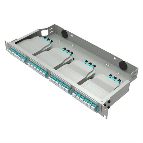
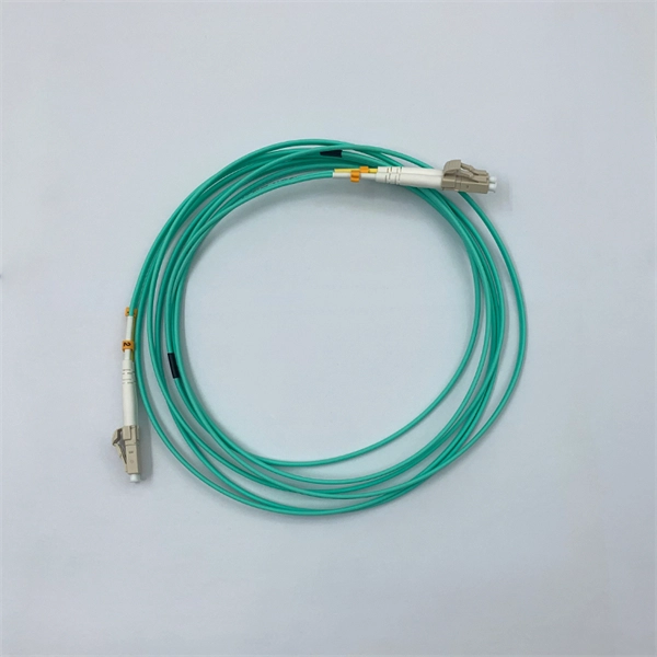
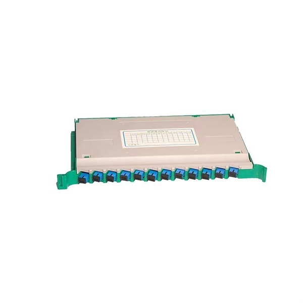
Proper fiber optic termination is a crucial process for ensuring the reliability, performance, and long-term durability of any fiber optic network. The process of fiber optic cable termination is the essential act of connecting fiber optic cables to devices, patch panels, or other. Fiber optic joints or terminations - where cables are terminated - are made two ways: 1) connectors that mate two fibers to create a temporary joint and/or connect the fiber to a piece of network gear (left) or 2) splices which create a permanent joint between the two fibers (right). Thus, you will put the cable across the points, stretch it to determine length, cut it accordingly, and place the connector on each end. After that, the patch panel attaches to it. Each cable has a connector attached. A. Once fiber optic cables have been successfully placed, we can focus on managing the ends of the fibers. This process depends on the project's needs and identifying a solution that aligns with the current situation. We can make suggestions that typically benefit the current circumstances and result. Where copper twisted pairs tend to terminate with an RJ45 plug, fiber optic connectors come in all sorts of shapes and sizes, with all manner of different use cases in mind. An optical fiber connector is used to join optical fibers where a connect/disconnect capability is required.
[PDF]
This post is a step-by-step detailed installation guide on how to run wires for security cameras to help you install security camera wiring for both indoors and outdoors. Proper wiring is crucial to ensuring that your security cameras function effectively and provide clear, uninterrupted footage. How to connect your cameras and recorder to provide power and a video feed, including for remote viewing via smartphones and computers. We always recommend wired systems when possible. We offer two different types of wired security camera systems -. There are two different ways to install security camera wiring: POE security camera wiring and wireless security camera wiring. Whether you're securing your home or business, the quality and installation of your camera wiring play a crucial role in ensuring consistent, high-quality video feeds. In this guide, we. This article provides a detailed principle explanation of 3R methods (reamplification, reshaping, and retiming) to reach the extension of passive optical networks. The second part of the article focuses on optical amplifiers, their advantages and disadvantages, deployment, and principles. We. In this step-by-step guide, we will walk you through the process of wiring your 2 wire security camera, providing you with a clear understanding of the necessary steps and a helpful diagram to refer to.
[PDF]
FTTH clamps are specialized devices designed to hold and secure fiber optic strands within an installation. These clamps not only protect the delicate optical cables from damage but also maintain proper alignment, which is vital for signal integrity. “Securing” fiber optic cable goes beyond just preventing it from moving; it encompasses protecting its delicate core from physical stress, environmental degradation, and ensuring long-term signal integrity. Achieving this requires a combination of thoughtful design, appropriate materials, and. OPGW is primarily used by the electric utility industry, placed in the secure topmost position of the transmission line where it “shields” the all-important conductors from lightning while providing a telecommunications path for internal as well as third party communications. With a combination of stainless steel wire and reinforced nylon body, Fibeye tension clamps offer excellent durability and performance. Do you need a reliable, durable, and. Fasclamp is a fiber optic cable clamp that is used to secure the fiber cables and prevent movement while prepping and splicing fiber cables. Designed by a by a fiber splicer with 25 years experience in the field, FasClamp and FasclampXL can be used in any splicing vehicle, trailer, or table mounted. Fiber optic cable clamps are devices used to secure and stabilize fiber optic cables in a wide range of applications, including telecommunications, data centers, and network systems.
[PDF]
Each wire must connect to its appropriate terminal: Live wires (red or brown) connect to the MCB's live terminal. Neutral wires (black or blue) go to the neutral bus bar. Welcome to our channel! In this video, we'll walk you through the process of wiring a home distribution box with a detailed connection diagram. Whether you're an electrician or a DIY enthusiast, this guide will. This guide provides step-by-step instructions for connecting a distribution box and highlights key factors to consider during installation. What Is a Distribution Box? A distribution box, also known as an electrical distribution board, is a critical component in electrical systems. In Single Phase supply (230V in UK, EU and 120V & 240V in the US & Canada), there are two (one is Line (aka Phase, Hot or Live) and the other one is Neutral) incoming cables from the utility poles to the kWh energy. A distribution board or distribution box is where the main power supply is distributed to multiple loads. And all the switching and protective devices are installed in the distribution box. Single Phase Distribution Box generally consists of Double Pole MCBs, Single Pole MCBs, and RCCBs.
[PDF]