Mouser offers inventory, pricing, & datasheets for Fiber Optic Sensors. Pricing (USD) Filter the results in the table by unit price based on your quantity. A tariff of 8% may be applied if shipping to the United States. The Optilab FOCS-1550-PG is designed for fiber optic current sensing. This device is composed of a polarizer, a Y-junction coupler and dual electro optic phase modulators. Based on Lithium Niobate (LiNbO3), FOCS-1550-PG is fabricated with Annealed Proton Exchange (APE) optical waveguides. The. The FOCS Series Fiber Optical Current Sensors are passive, all-dielectric devices designed for precise current measurement without metal components, making them immune to electromagnetic interference noise. They measure current using light that passes through a Faraday fiber and reflects back from. A fiber optic current sensor operates based on the Faraday effect, a magneto-optic phenomenon where the polarization plane of light rotates in proportion to the magnetic field generated by an electric current. These sensors are inherently immune to electromagnetic interference (EMI), making them. The global Fiber Optic Current Sensors (FOCS) market was valued at US$ 239. 6 million in 2023 and is projected to reach US$ 401. 5% during the forecast period.
[PDF]
Energy & Financial Markets: What Drives Crude Oil Prices? Greenhouse gas data, voluntary reporting, electric power plant emissions. Maps, tools, and resources related to energy disruptions and infrastructure. State energy information, including overviews, rankings, data, and. Energy is at the heart of today's geopolitical tensions, with traditional risks to fuel supply now accompanied by restrictions affecting supplies of critical minerals. International. The IEA examines the full spectrum of energy issues including oil, gas and coal supply and demand, renewable energy technologies, electricity markets, energy efficiency, access to energy, demand side management and much more. Through its work, the IEA advocates policies that will enhance the. The Energy Institute Statistical Review of World Energy™ analyses data on world energy markets from the prior year. Previously produced by bp, the Review has been providing timely, comprehensive and objective data to the energy community since 1952. By submitting your email you agree to receive. Reducing energy consumption and achieving energy savings is essential to deliver the European Green Deal. Energy from renewable sources reduces greenhouse gas emissions and lowers our dependence on imported fossil fuels.
[PDF]
This video shows real on-site footage of electrical installation, demonstrating safe and standardized wiring methods used by professionals. more Learn how to wire a distribution box step by step!. A distribution box, also known as a distribution board, electrical panel, or breaker box, is an enclosure that houses electrical components responsible for distributing electricity throughout a building. more Learn how to wire a distribution box step by step! This video shows real on-site footage of. In this video, we'll walk you through the process of wiring a home distribution box with a detailed connection diagram. Whether you're an electrician or a DIY enthusiast, this guide will help you understand the basics of home electrical distribution. What is Distribution Board? Distribution board. Connection method: Each switch takes a wire from the incoming point and connects it to the incoming end of the switch, or uses parallel connection to reduce the difficulty of wiring. Wiring Direction: Wiring between the main circuit breaker and each branch circuit breaker in the box generally. Understanding the wiring diagram of an electrical panel box is essential for electricians and homeowners alike, as it allows them to troubleshoot any electrical issues, carry out repairs, or make additions to the system. It takes the incoming power and safely distributes it to different circuits throughout your building. However, the key to.
[PDF]
It works on the principle of sensing residual current which is why it is called a residual current device. Nowadays, all domestic and commercial electrical systems and circuits use RCDs. Today, we will see how you can connect an RCD to the distribution . Hey, in this article we are going to see the RCD Wiring diagram and its connection procedure. RCD means Residual Current Device. It is an electrical protective device that protects electrical circuits and devices from some electrical faults such as leakage faults, electrical shock, current. Distribution board is a safe system designed for house or building that included protective devices, isolator switches, circuit breaker and fuses to connect safely the cables and wires to the sub circuits and final sub circuits including their associated Live (Phase) Neutral and Earth conductors. Residual-current devices, commonly referred to as RCDs, are used in many practical applications. They can be found in fuse boxes, electrical switchgears or industrial machine control systems. Therefore. A distribution box uses MCBs, RCDs, and busbars to protect circuits, prevent shocks, and ensure safe power distribution in homes and buildings. This box keeps your home or building safe from electrical dangers. Devices that operate with electricity can cause leakage due to various reasons. If this leakage is not detected and cut off in time, it can lead to.
[PDF]

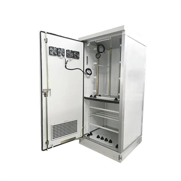
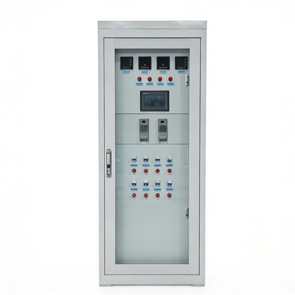
Residual current devices (RCDs) at both the tertiary (equipment-level) and secondary (zone-level) stages. Ensures safe disconnection in case of faults or leakage currents. A distribution box is installed under the main distribution box, and a switch box is installed under the distribution box. These boxes feature bottom entry and exit cables, front-opening doors, and main busbars connected with copper strips for optimal contact. They also include metering systems, ensuring. In a newly constructed residential area, a 10kV power line is introduced into the substation. After stepping down the voltage through the transformer's low-voltage side (0. 4kV), power distribution is achieved through three levels of distribution boxes: the main distribution board, secondary. Equipment inside usually includes isolating switches, circuit breakers, and residual current devices (RCDs). Supplies power to specific buildings or floors. It is specially designed for the special situation of the project construction site and meets the relevant construction power specifications and standards of the. A distribution board (also known as panelboard, circuit breaker panel, breaker panel, circuit breaker, electric panel, fuse box or DB box) is a component of an electricity supply system that divides an electrical power feed into subsidiary circuits while providing a protective fuse or circuit.
[PDF]
The Optical Time Domain Reflectometer (OTDR) is useful for testing the integrity of fiber optic cables. It can verify splice loss, measure length and find faults. in cable TV, LAN, metropolitan networks or long-haul. Ensure the integrity of your fiber optic network with an Optical Time Domain Reflectometer (OTDR). OTDR testing analyzes fiber optic cable performance from end to end by testing components along the cable, including connection points, bends, and splices. It injects a series of optical pulses into the fiber and analyzes the backscattered signal based on time, enabling a detailed view of the. 15 EXFO Inc. No part of this publication may be reproduced, stored in a retrieval system or transmitted in any form, be it electronically, mechanically, or by any other means such as photocopying, recording or otherwise, without the prior writt eved to be accurate and reliable. From a single end of the link, it can determine the magnitude and location of loss, detect reflections, and visualize events along the fiber. An OTDR injects a series of optical.
[PDF]
This map shows where fiber internet service is available across the United States from all providers. Use the map controls to color by number of fiber providers or by maximum fiber speed available. Fiber-optic internet is the fastest and most reliable type of internet connection available. The map will be updated continuously to improve its accuracy through a combination of FCC verification efforts, new data from Internet. Fios is currently available in the metro areas below. Don't see your town? Check additional locations here. So you can binge, game and work at the speed you need. No unexpected price hikes, hidden fees, or equipment charges. Get a Wi-Fi Extender.
[PDF]
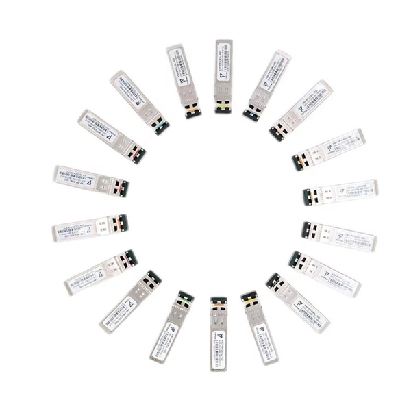
The QSFP28 transceiver provides 100GBase-BX throughput up to 20km over single-mode fiber (SMF) using a wavelength of 1310nmTx/1280nmRx via an LC connector. This bidirectional unit must be used with another transceiver or network appliance of complimenting wavelengths. Whether it's building a network or upgrading an existing network, the Cisco® QSFP-100G-B20U4-I and QSFP-100G-B20D4-I transceivers provide 100G connectivity for platforms at up to 20km on single SMF (Single Mode Fiber). This. The QSFP-100G modules are our latest generation of 100G transceiver modules solution based on a QSFP form factor. Table 1 describes the Cisco QSFP-100G portfolio. Cisco QSFP-100G Portfolio The Cisco 100GBASE-SR4-S QSFP Module supports link lengths of up to 70m. To meet the demand for long-distance transmission in scenarios where optical fiber resources are scarce in edge access networks, Walsun has launched the 100G QSFP28 ZR4 BIDI product, and will demonstrate 100G 80km single-fiber bidirectional service transmission at OFC 2024. 66nm-RX) via an LC. NEC's 100G QSFP28 BiDi optical transceiver enables the transmission and reception of 100Gb/s high-speed data over a single optical fiber. By enabling bidirectional transmission over a single fiber, this module enhances fiber utilization efficiency and can reduce fiber costs. ZR4 BiDi, using four.
[PDF]
Protection is accomplished by application of a definite time overcurrent option. Current setting is greater than full load current but is lower than the motor starting current. Should a motor stall whilst running, or fail to start, due to excessive. When a motor starts, it can draw 6-8 times its full-load current for a brief period, creating significant challenges for circuit protection, voltage regulation, and system capacity planning. Understanding motor starting characteristics is essential for proper breaker sizing, motor protection relay. These time-overcurrent elements support the IEC and U. (IEEE) time-overcurrent characteristics. Electromechanical disc reset capabilities are provided for all time-overcurrent elements. protection and fault clearance in abnormal situations. The main features of the motor relay include thermal overload protection, motor start-up time supervision, locked rotor protec ion, and protection against too frequent motor starts. Addi ionally, differential protection can also be included. In order to prevent damage to the contactor, the maximum peak let-through current (Ip ) and maximum clearing energy (I2t) (amps2 seconds) of the fuse must be less than the equivalent ratings for the contactor. The clearing time and let-through characteristics of the fuse must be considered when.
[PDF]
This section provides a list of the top 10 Optical Time Domain Reflectometer manufacturers, Website links, company profile, locations is provided for each company. Optical Time Domain Reflectometers (OTDR) are instruments used for detecting and analyzing scattered or back-reflected light within optical fibers, pinpointing impurities and imperfections. Also provides a detailed product description of the Optical Time Domain Reflectometer, including product introduction, history. An optical time-domain reflectometer (OTDR) is an optoelectronic instrument used to characterize an optical fiber. It is the optical equivalent of an electronic time domain reflectometer which measures the impedance of the cable or transmission line under test. It can offer you an overview of the whole system you test and can be used for estimating the fiber length and overall attenuation, including splice and mated-connector losses.
[PDF]

The total interruption time for a modern high-voltage SF6 circuit breaker is typically between 40 to 60 milliseconds on a 50Hz grid, or 2 to 3 cycles. This is the total time from the trip signal to the final arc extinction, a critical parameter for grid safety. While knowing the total time is a. When a SF6 circuit breaker (CB) hits its critical low pressure, its fault interrupting capability can be compromised. Most TOs protect against this by either auto-opening the CB prior to reaching the critical low-pressure level or by blocking the CB from tripping (when it reaches the critical. The protected zone is defined and limited by different things depending on the protection function. Definite time delay means that the protection operate time dose not change or depend on the fault type or the fault current magnitude. Instead of oil, air, or a vacuum, a sulfur hexafluoride circuit breaker uses sulfur hexafluoride (SF 6) gas to cool and quench the. Page 1 Content Instruction Manual circuit- breaker GL317 With spring operating mechanisms FK3- 4 Administrator First issue Compiled by Approved by 19- 11- 2012 J. Texier Imagination at work Grid Solutions 04- 2017 D1736EN/03 GE Information 1/10. Page 2 Content Instruction Manual This. A comparison of the time it takes protective devices to operate when certain levels of normal or abnormal current pass through them. LV circuit breaker ratings.
[PDF]