These modules are engineered with high-grade components designed to withstand the vibrations of washboard forest service roads and the temperature swings of high-altitude passes. 00 Original price was: $46. Activates High current relay when High Beams are turned on, used to add large light bars and driving lights without having to install additional switches in the dash. Plugs directly into Polaris Pulse System for switch lighting and keyed on ignition. The CanM8 Cannect Duo (Speed Pulse & High Beam) Interface is a 2-output CAN Bus interface which provides a quick solution for detecting high beam activity on vehicles which feature CAN Bus wiring. The Cannect Duo Interface also features a square pulsed speed signal output from the vehicle at a. Electronic technology has advanced so that an electronic control unit (ECU) is required to control the functions of full LED automotive headlights. An ECU consists of mainly LED drivers for headlight functions such as high beams, low beams, daytime running lights, position lights, turn indicators. This module resolves the issues with the headlight turning off, or flashing after the ignition is turned on. This issue is mainly affecting Chrysler, Jeep, Dodge vehicles, but some other modern cars will have this same issue. They offer a true plug-and-play experience, effectively eliminating the common flickering issues associated with.
[PDF]
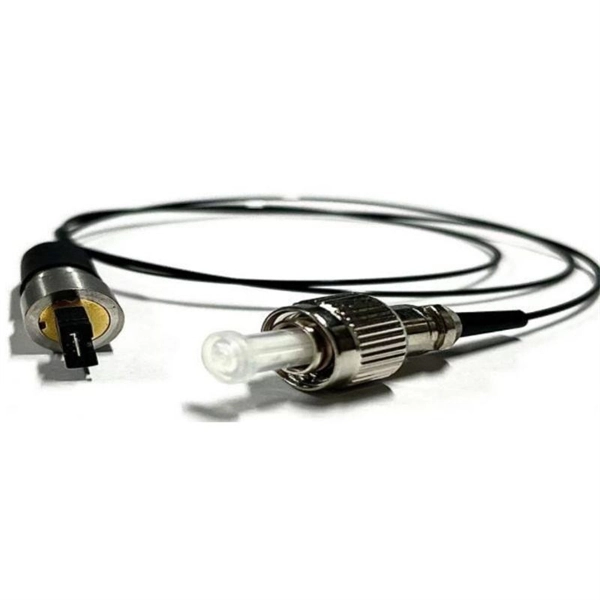
A variety of optical fiber connectors are available, but SC and LC connectors are the most common types of connectors on the market. Typical connectors are rated for 500–1,000 mating cycles. The main differences among types of connectors are dimensions and. An optical fiber connector is a device used to link optical fibers, facilitating the efficient transmission of light signals. They come in various types like SC, LC, ST, and MTP, each designed for specific. Fiber connector types LC, SC, FC, ST, MTP, and MPO are widely used in past and present. What are the differences between them? Who is the most popular one? Find the answer in the article. What is a Fiber Connector? The optical fiber connector is a kind of detachable passive optical component used. Fiber optic cable assembly quality hinges on selecting the right connector type—most commonly LC, SC, or ST—to match device ports and installation environment. When selecting the appropriate optical module for a network application, one crucial factor to consider is the type of fiber connector it employs. Fiber optic connectors are used to the mechanical and optical means for cross connecting fibers. There have been many types of connectors developed for fiber cable. With the demands of different application scenarios.
[PDF]
It supports multi-mode fiber with a reach of 300m via a duplex LC connector. Designed for extended temperatures (-40°C to 85°C), it includes Digital Optical Monitoring (DOM) and guarantees full compatibility with H3C equipment, making it ideal for harsh environment deployments. Optical modules transmit signals over optical fibers. Optical transmission features low loss and is fit for long distance transmission. The. Max. Note: Due to DigiKey value-add services the packaging type may change when product is purchased at quantities beneath the standard package. Buy now, ships today. SFP-XG-SX-MM850-D-C - Transceiver Module Networking and Communications 10Gbps 850nm LC Duplex Pluggable, SFP+ from ATGBICS. View. This H3C® SFP-XG-SX-MM850-A compatible SFP+ transceiver provides 10GBase-SR throughput up to 300m over multi-mode fiber (MMF) using a wavelength of 850nm via an LC connector. Our transceiver is built to meet or exceed OEM specifications and is guaranteed to be 100% compatible with H3C®. With a data rate of 10. This transceiver is compliant with SFF-8431, SFF-8432 and IEEE 802. 3ae standards and for seamless interoperability in multivendor environments.
[PDF]
Joints between high-current bus sections often have precisely machined matching surfaces that are silver-plated to reduce contact resistance. At extra high voltages (more than 300 kV) in outdoor buses, corona discharge around the connections becomes a source of radio-frequency interference and power loss, so special connection fittings designed. OverviewIn , a busbar (also bus bar) is a metallic strip or bar, typically housed inside,, and for local high current power distribution, transmission, or switching s. The busbar's material composition and cross-sectional size determine the maximum current it can safely carry. Busbars can have a cross-sectional area of as little as 10 square millimetres (0.016 sq in), but. • – Data transfer channel connecting parts of a computer• – Low resistance electrical conductor for high current transmission and distribution• – Modular approach t.
[PDF]
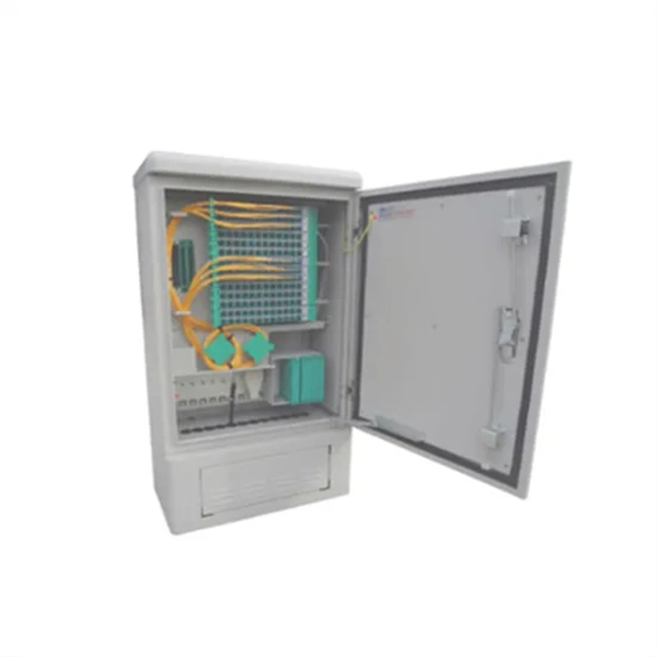
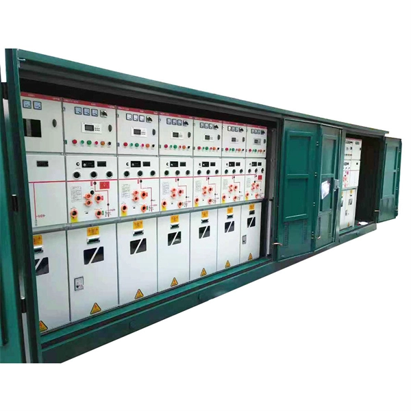
Marker balls, also known as aerial marker balls or power line marker balls, are brightly colored spherical objects attached to overhead power lines. These balls are made of durable, light materials like plastic or rubber. As a key electrical equipment for receiving and distributing high-voltage electric energy in the power system, the high-voltage distribution cabinet plays an indispensable role in the safe and stable operation of the power system. There are many types of components in the cabinet, and each has a. A distribution box is a key part of electrical systems in buildings. It helps control and distribute electricity to different areas. Inside, you'll find parts like circuit breakers and fuses that protect the system from problems like overloads and short circuits. Today, electrical systems are essential for homes and industries. But what exactly is a power distribution box, and why is it so essential in our daily lives? The DB panel board controls the flow of electricity. In a substation there are numbers of incoming and outgoing circuits each having its isolator, circuit breaker, transformers etc. connected to bus-bar system. These equipment are mostly static.
[PDF]

A protection relay tripping circuit connects relays to breakers for fast fault isolation. Key components include trip/close coils and anti-pumping relays. Proper design, testing, and maintenance ensure reliable overcurrent, differential, and auto-reclosing protection in power. The protection relay tripping circuit refers to the critical electrical control loop that executes trip/close commands from protective relays to circuit breakers, ensuring rapid fault isolation in power systems. Essential. Electromechanical protective relays at a hydroelectric generating plant. The relays are in round glass cases. In electrical engineering, a protective relay is a relay device. A protective relay is an intelligent electrical device designed to detect faults in power systems and initiate corrective actions such as tripping a circuit breaker. Its main purpose is to safeguard electrical equipment like transformers, generators, and transmission lines from damage due to. By definition, a protective relay is a switchgear device that detects faults and initiates the circuit breaker operation to isolate the problematic component of the system. Electrical values are measured by these relays to determine abnormal circumferences of a circuit. It functions as a watchdog by constantly surveying multiple system components including voltage, current, frequency, and phase angle.
[PDF]
As illustrated in typical SFP internal structure diagrams, the module's core components include an optical transmitter assembly (TOSA), laser driver, optical receiver assembly (ROSA)—some high-sensitivity modules (like L16. 2) use APD receivers, which require an additional booster. As a key element in optical communication systems, optical transceivers serve as media between network devices to transmit and receive data. There has been lots of articles and guides on transceiver modules in the perspective of the package type while only a few of them cover the internal elements. Optical modules are devices used to connect network devices, transmit and receive data between network devices, and can be used to convert optical and electrical signals. The optical module is a very important component in an optical communication system. When you remove the metal housing of the optical transceiver, you will find that the internal components are connected to each other. The following section will focus on. In the era of 5G, AI, and high-speed data centers, optical modules serve as the core bridge for converting electrical signals to optical signals (and vice versa), enabling fast, reliable data transmission across networks. Among various optical module form factors, SFP (Small Form-Factor Pluggable). The optical transceiver module is mainly composed of three parts: housing, optical device and integrated circuit board. The following section will focus on.
[PDF]
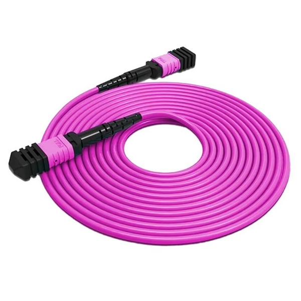
Fiber optic "cable" refers to the complete assembly of fibers, other internal parts like buffer tubes, ripcords, stiffeners, strength members all included inside an outer protective covering called the jacket. Cable provides protection for the optical fiber or fibers within it appropriate for the environment in which it is installed. You will also learn how different aspects of the product can affect budget and design. ■ The Five Key Parts of a Fiber Optic Cable A fiber optic cable. A fiber optic cable consists of five basic components: the core, the cladding, the coating, the strengthening fibers, and the cable jacket. When searching for a fiber optic cable, we need to pay attention not only to the connectors, such as SC to ST fiber cable, LC to SC fiber patch cable, or SC to. A TOSLINK optical fiber cable with a clear jacket. These cables are used mainly for digital audio connections between devices. This advanced cabling solution allows fast, secure data transfer and telecom over long distances. Understanding the components within a fiber optic cable enables. While fiber optic cable itself is cheaper than an equivalent length of copper cable, fiber optic cable connectors and the equipment needed to install them have typically been more expensive than their copper counterparts.
[PDF]
Follow a clear step-by-step process: install the ground rod deeply, connect the grounding wire securely, attach it to the panel's ground bus bar, and test the system with proper equipment. Installed correctly, grounding wire can prevent electrical shocks or fires at homes or in offices. This guide reviews the basics of electrical grounding, how to safely ground wiring and how to check if wire is grounded. SHOP GROUNDING WIRES NOW Why Does Wiring Need to be Grounded? Install grounding. However, for experienced DIYers, this guide provides a detailed, step-by-step approach to ensuring your circuit breaker box is properly grounded, enhancing electrical safety grounding throughout your home. It. Section 250. For grounded systems, the NEC requires you to perform all of the following: electrical system grounding, electrical equipment grounding, electrical equipment. Drive a ground rod into the earth and attach a grounding wire to the main electrical panel to add grounding to an existing panel. Install new outlets with a continuous grounding connection to the grounding rod. In this post, I'll go through why every electrical panel should be grounded, what ground. The correct connection method of Distribution box grounding wire mainly includes the following steps: 1. Find the grounding bar or PE bar Open the distribution box and find the position marked with the grounding plate or PE letter.
[PDF]
Find and discover Fiber Optic manufacturers and suppliers for all products in Laos, featuring details on their shipment activities, trade volumes, trading partners, and more. View all fiber optic buyers based on products in Laos. Subscribe to global trade data intelligence to discover new business. WWCC is upgrading the products operations through research, advanced technology and machinery, to serve the expanding needs of Laos's economy at competitive prices. The company is committed to offer high quality products to achieve customers' satisfaction. Our fiber optic cables are designed for use in laser surgery, endoscopy, photodynamic therapy, and diagnostic imaging, ensuring superior light transmission. How does 6W market outlook report help businesses in making decisions? 6W monitors the market across 60+ countries Globally, publishing an annual market outlook report that analyses trends, key drivers, Size, Volume, Revenue, opportunities, and market segments. Our insights help.
[PDF]
At present, key breakthroughs in optical fiber communication technology include high-order modulation formats, polarization multiplexing, wavelength division multiplexing, etc. Optical fiber communication can be widely applied in the fields of the internet and telephone networks . With the rapid development of cloud computing, big data, the Internet of Things, and other new technologies, we have entered an era of digitalization and informatization. The number of internet users has been steadily increasing, which has accelerated the exponential expansion of data services. A. Then the different technologies in optical fiber communication along with their features are discussed briefly.
[PDF]
Fiber optic pigtails are roughly divided into two categories: Multimode and single-mode fiber pigtails. Multimode pigtails consist of 62. 5 or 50-core multimode fiber optic cables that are terminated with multimode connectors. To classify them further, they can be subdivided into OM1. This guide covers everything: what fiber optic pigtails are, how they differ from patch cords, which connector and polish type to specify, how to choose between mechanical and fusion splicing, and the real-world applications where pigtails are the right call. Whether you're building out an ODF. A fiber optic pigtail is a short length of optical fiber —typically 0. 5m to 2m—that has a factory-terminated connector on one end and bare fiber on the other end. The connector end is polished and tested under factory conditions, ensuring low insertion loss and high return loss. The bare fiber end. Understanding the different models and characteristics of fiber pigtails can help users better match system requirements in practical applications and ensure efficient and stable fiber optic communications. The connector end can be linked directly to network equipment, while the exposed end can be spliced to another fiber optic cable. In this comprehensive guide, we explore the different types of fiber optic pigtails available, including MU, LC, SC, FC, DIN, APC, and UPC.
[PDF]
The V-groove substrate is the heart of the Fiber Array, providing precise alignment for the optical fibers. This substrate, typically made from silicon, glass, or ceramic, features a series of V-shaped grooves etched with sub-micron accuracy. Fiber Array (FA for short) is an array formed by installing a bundle of optical fibers or a fiber ribbon on the substrate at specified intervals by using a V-Groove (V-Groove) substrate. Fiber optic arrays in optical communications mainly include a substrate, a platen, and an optical fiber. Whether integrated into planar lightwave circuits (PLCs), optical switches, or high-speed transceivers, FAs play a vital role in ensuring. What is a Fiber Array (FA)? A Fiber Array, commonly abbreviated as FA, is a critical interface component in Silicon Photonics (SiPh) packaging, Photonic Integrated Circuits (PIC), and Co-Packaged Optics (CPO) architectures. It is responsible for efficiently coupling "external optical fibers" with. Fiber Arrays (FAs), as high-precision, high-performance optical components, have become indispensable core elements in fields such as optical communications, photonic integration, and laser processing. Typically, such an array is formed only for the very end of the fibre bundle, rather than over the entire length of the.
[PDF]
39 A/mm² is safely below the typical 1. The busbar must survive the heat from a short-circuit fault. Use the IEC 60949 adiabatic formula: $S ge frac {I_k times sqrt {t}} {k}$. Since 1. Instead of using many separate wires, a busbar provides a single, organized path for carrying high current between different electrical components. Bus bars are the essential components in the electrical distribution systems (EDB) serving as primary conductors that carry current between 1). Circuit breakers, 2). Proper sizing is the essential for safety, efficiency and compliance with international electrical. Click Calculate to see the required area and recommended size. Full IEC Verification Enter your base parameters as in the standard method. This disables the safety factor and reveals IEC-specific inputs. Enter derating factors, short-circuit current. The Busbar Size Calculator helps engineers and electricians find the right copper or aluminum busbar dimensions based on current capacity, material type, and environmental conditions. The current rating is calculated from the conductor cross-sectional area, material (copper or aluminium), and maximum. A bus bar is a solid bar or metallic strip that is used for power distribution. Busbars have extensive use inside panel boards, busways, and switchgears. The busbars of right sizes ensure a safe and secure current distribution with ease and flexibility. We can consider a busbar as a node or a group.
[PDF]
Recommendation ITU-T G. 654 describes the geometrical, mechanical and transmission attributes of a single-mode optical fibre and cable which has the zero-dispersion wavelength around 1300 nm wavelength, and which is loss-minimized and cut-off wavelength shifted at around the 1550 nm. Recommendation ITU-T G. 649 Optical fibre cables G. 659 Characteristics of optical components and subsystems Characteristics of optical systems G. 679. In recent years, a new type of G. E optical fibre has started to be used in some long-distance trunk lines, and has achieved better results. 654 fibre In the mid-1980s, in. As a leading fiber optic manufacturer with 21 years of experience, GL FIBER specializes in producing high-performance G. C, for long-haul and high-speed networks. Below, we explain the technical differences between these two fiber types to help you choose the. uous requirements for higher capacity optical transmission systems. To support these high capacity systems in terrestrial backbone networks, low attenuation and large core area fibers compliant with Recommendation ITU-T G 654. E were introduced and have been extensively deployed worldwide. For this protective layer, Sumitomo Electric utilizes a dual-layer acrylate coating structure. The precisely controlled coating diameters and the exceptional.
[PDF]