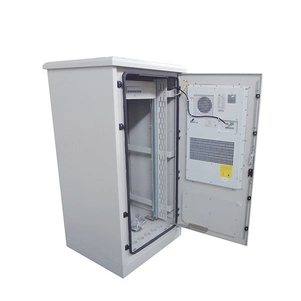
The base station can be divided into two modules: the RRU for transmitting signals and the BBU for processing signals. The BBU is small and exquisite, with low power consumption, while the RRU is large and has high power consumption. Which optical modules are commonly used in 4G base stations? In this blog, ETU-LINK will talk about 4G base stations and common types of optical modules. The BBU is small and. In a mobile communication base station, the antenna is at the top of the signal tower, and under the tower is the machine room, in which the base station is placed. Generally, the. RRU and BBU are crucial components in base station construction, enabling a distributed architecture that improves efficiency and reliability. Here's a breakdown of each: The central processing unit in a base station. Handles baseband signal processing, transmission scheduling, and network interfacing. BBU is used for signal processing, RRU is used for signal transmission and reception, and the feeder is used to connect the antenna and the base. The base station is logically divided into two parts: BBU and RRU. RRU is responsible for signal transmission and reception, and BBU is responsible for signal processing. The feeder is used to connect the antenna and the base station, and the supporting equipment is mainly the power supply and air.
[PDF]
These modules are engineered with high-grade components designed to withstand the vibrations of washboard forest service roads and the temperature swings of high-altitude passes. 00 Original price was: $46. Activates High current relay when High Beams are turned on, used to add large light bars and driving lights without having to install additional switches in the dash. Plugs directly into Polaris Pulse System for switch lighting and keyed on ignition. The CanM8 Cannect Duo (Speed Pulse & High Beam) Interface is a 2-output CAN Bus interface which provides a quick solution for detecting high beam activity on vehicles which feature CAN Bus wiring. The Cannect Duo Interface also features a square pulsed speed signal output from the vehicle at a. Electronic technology has advanced so that an electronic control unit (ECU) is required to control the functions of full LED automotive headlights. An ECU consists of mainly LED drivers for headlight functions such as high beams, low beams, daytime running lights, position lights, turn indicators. This module resolves the issues with the headlight turning off, or flashing after the ignition is turned on. This issue is mainly affecting Chrysler, Jeep, Dodge vehicles, but some other modern cars will have this same issue. They offer a true plug-and-play experience, effectively eliminating the common flickering issues associated with.
[PDF]
Joints between high-current bus sections often have precisely machined matching surfaces that are silver-plated to reduce contact resistance. At extra high voltages (more than 300 kV) in outdoor buses, corona discharge around the connections becomes a source of radio-frequency interference and power loss, so special connection fittings designed. OverviewIn , a busbar (also bus bar) is a metallic strip or bar, typically housed inside,, and for local high current power distribution, transmission, or switching s. The busbar's material composition and cross-sectional size determine the maximum current it can safely carry. Busbars can have a cross-sectional area of as little as 10 square millimetres (0.016 sq in), but. • – Data transfer channel connecting parts of a computer• – Low resistance electrical conductor for high current transmission and distribution• – Modular approach t.
[PDF]
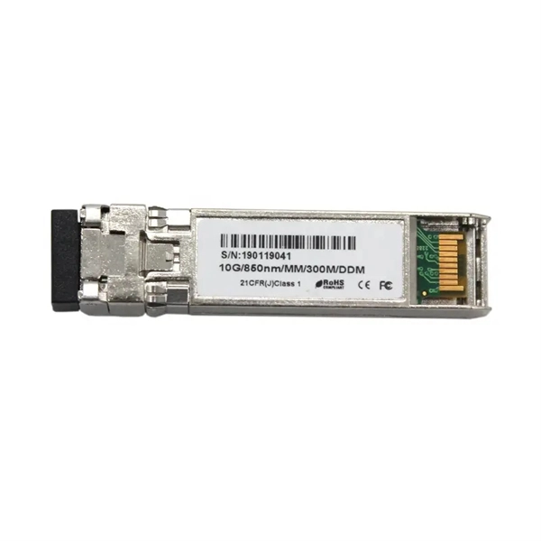
Description: Explore how optical modules enable high-speed data conversion across data centers, 5G networks, storage systems, and WDM applications. Learn about SFP, SFP28, CWDM, and DWDM solutions. Optical modules are widely used in various industries. Aerech Networks will use this article to introduce you to the application scenarios of optical modules. Optical modules are critical components in modern data communication, serving to convert electrical. Optical module is mainly used in the field of data communication. Its function is to realize the mutual conversion of photoelectric signals. Due to the rise of big data, blockchain, cloud computing, Internet of things, artificial intelligence and 5G, data traffic has increased rapidly. As the demand for faster and more reliable internet and data services grows, understanding these devices becomes increasingly important. This guide will explore. What You'll Learn in This Guide By reading this article, you will: By the end, you'll have a clear, expert-level understanding of CFP optical modules—and more importantly, the confidence to decide whether they are the right fit for your specific application.
[PDF]
Underground fiber optic cable installation follows specific standards that govern burial depth, testing methods, installation techniques, and safety requirements. Underground cables are pulled in conduit that is buried underground, usually 1-1. 2 meters (3-4 feet) deep to reduce the likelihood of accidentally being dug up. In extreme cold climates, cables may need to be buried at greater depths where there temperatures are colder and frost penetrates to. The Fiber Optic Association, Inc. (FOA) was founded in 1995 to help develop the workforce to build the fiber optic networks to support a rapid expansion in communications and the Internet. The charter of the FOA was to promote professionalism in fiber optics through education, certification, and. This guide walks through each stage of underground fiber installation—from route planning and conduit selection to splicing, termination, and testing—to help ensure long-term network performance and reliability. These standards, established by organizations like the National Electrical Code (NEC), National Electrical Safety Code (NESC), and. Installing underground fiber optic cables is critical to establishing high speed internet infrastructure that delivers reliable connectivity for businesses nationwide. Unlike traditional copper systems, fiber optic cables require specialized handling techniques and precise installation methods to.
[PDF]
The vertical clearance for overhead fiber optic lines above the highway must be a minimum of 18 feet. The exception is ADSS cables which are approved for installation in the power space by qualified personnel. All aerial cables should be installed clear of any obstructions. The Fiber Optic Association, Inc. (FOA) was founded in 1995 to help develop the workforce to build the fiber optic networks to support a rapid expansion in communications and the Internet. The charter of the FOA was to promote professionalism in fiber optics through education, certification, and. The basic pole height is 7m and the tip diameter is 150mm. In case of special sections, crossing obstacles or roads or railways, the pole height of 8m, 9m, etc. can be selected according to the actual terrain. If the surface is stone, the depth needs to be 0. 9m, and if the surface is other soil. Generally a 12 inch to 24 inch soil separation is recommended as a safety barrier and for locating purposes. 9938 | SuperiorEssexCommunications. com Page 1 of 4 TECHNICAL GUIDELINE July 30, 2020 TG030 Rev. FIBER is used for relocating any fiber optic cable from one location to another. Field conditions will vary, so the actual location. to n utral comm.
[PDF]
At present, key breakthroughs in optical fiber communication technology include high-order modulation formats, polarization multiplexing, wavelength division multiplexing, etc. Optical fiber communication can be widely applied in the fields of the internet and telephone networks . With the rapid development of cloud computing, big data, the Internet of Things, and other new technologies, we have entered an era of digitalization and informatization. The number of internet users has been steadily increasing, which has accelerated the exponential expansion of data services. A. Then the different technologies in optical fiber communication along with their features are discussed briefly.
[PDF]
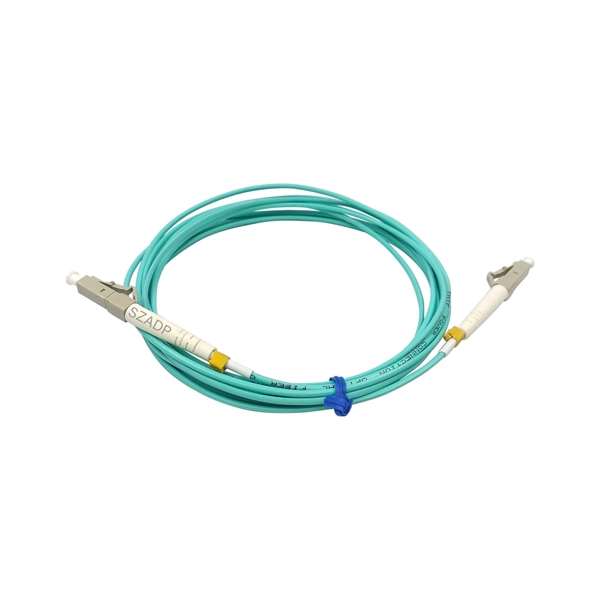
Several common cable outer sheath materials are PVC, PE, LSZH, AT and rodent-proof sheath materials. PVC is the most widely used fiber optic cable outer sheath material. What Is a Cable Sheath and Why It Matters 🔍 The cable sheath is the outer protective layer of a fiber optic cable. Its primary functions include: While the optical fiber itself remains largely unchanged, the sheath material determines how the cable behaves in fire scenarios, outdoor environments. The main function of the fiber cable outer sheath is to protect the optical fibers in the optical cable from external damage. At the same time, it must have. PVC vs LSZH vs TPU: Which sheath material for fiber optic cables in 2026? The jacket material determines the reliability, fire resistance, and lifespan of a fiber optic cable. At the same time, it must have. If so, then do remember that Fiber cables are made with high-grade glass cores and environmental protective sheaths, which can endure everything from residential network connections to underwater links. In this article, we'll discuss in detail the construction of Fiber optic cables and also see the. The sheath or outer sheath is the outermost protective layer in the optical cable structure, mainly made of PE sheath material and PVC sheath material, and halogen-free flame-retardant sheath material and electric tracking resistant sheath material are used in special occasions.
[PDF]
Follow a clear step-by-step process: install the ground rod deeply, connect the grounding wire securely, attach it to the panel's ground bus bar, and test the system with proper equipment. Installed correctly, grounding wire can prevent electrical shocks or fires at homes or in offices. This guide reviews the basics of electrical grounding, how to safely ground wiring and how to check if wire is grounded. SHOP GROUNDING WIRES NOW Why Does Wiring Need to be Grounded? Install grounding. However, for experienced DIYers, this guide provides a detailed, step-by-step approach to ensuring your circuit breaker box is properly grounded, enhancing electrical safety grounding throughout your home. It. Section 250. For grounded systems, the NEC requires you to perform all of the following: electrical system grounding, electrical equipment grounding, electrical equipment. Drive a ground rod into the earth and attach a grounding wire to the main electrical panel to add grounding to an existing panel. Install new outlets with a continuous grounding connection to the grounding rod. In this post, I'll go through why every electrical panel should be grounded, what ground. The correct connection method of Distribution box grounding wire mainly includes the following steps: 1. Find the grounding bar or PE bar Open the distribution box and find the position marked with the grounding plate or PE letter.
[PDF]
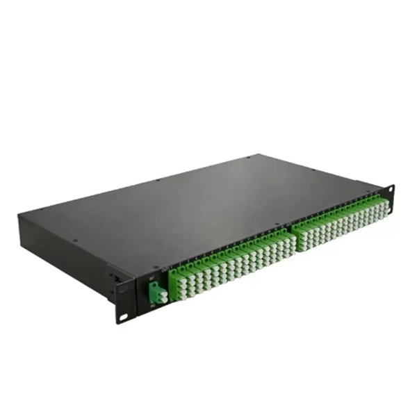
These characteristics make DST splitters suitable for optical benches and reference measurement systems, where lasers with low to medium power are split into multiple beams with minimal loss. DST beam splitters are designed for unpolarized light sources. A beam splitter or beamsplitter is an optical device that splits a beam of light into a transmitted and a reflected beam. It is a crucial part of many optical experimental and measurement systems, such as interferometers, also finding widespread application in fibre optic telecommunications. Beamsplitters are often classified according to their construction: cube or plate. Signal attenuation refers to the reduction in the intensity of a light beam as it passes through a medium or a device. When a beam splitter divides the incoming light. The Keysight Technology, Inc. family of high-performance beamsplitters offers industry-leading polarization and beam control with low wavefront distortion. For more than 35 years, Keysight has designed and produced beamsplitters exclusively for the most demanding custom interferometry applications. Cube beamsplitters avoid beam displacement by working at 0° angle of incidence and placing the coated surface between two right angle prisms, but power handling can be limited if epoxy is used to bond the prisms. Newport offers a wide variety of Beamsplitters in various shapes.
[PDF]
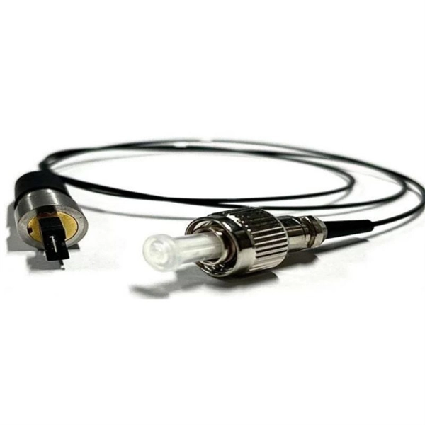
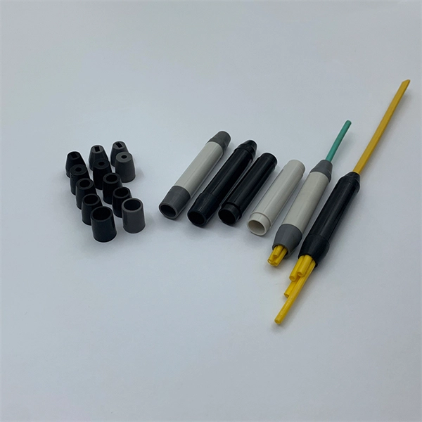
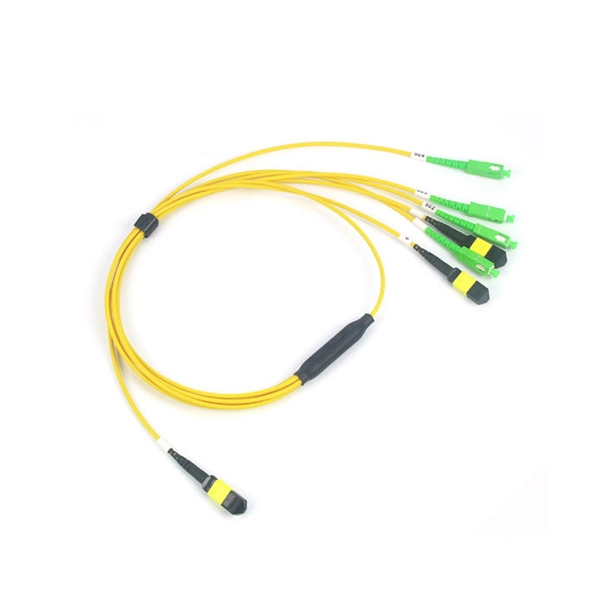
The V-groove substrate is the heart of the Fiber Array, providing precise alignment for the optical fibers. This substrate, typically made from silicon, glass, or ceramic, features a series of V-shaped grooves etched with sub-micron accuracy. Fiber Array (FA for short) is an array formed by installing a bundle of optical fibers or a fiber ribbon on the substrate at specified intervals by using a V-Groove (V-Groove) substrate. Fiber optic arrays in optical communications mainly include a substrate, a platen, and an optical fiber. Whether integrated into planar lightwave circuits (PLCs), optical switches, or high-speed transceivers, FAs play a vital role in ensuring. What is a Fiber Array (FA)? A Fiber Array, commonly abbreviated as FA, is a critical interface component in Silicon Photonics (SiPh) packaging, Photonic Integrated Circuits (PIC), and Co-Packaged Optics (CPO) architectures. It is responsible for efficiently coupling "external optical fibers" with. Fiber Arrays (FAs), as high-precision, high-performance optical components, have become indispensable core elements in fields such as optical communications, photonic integration, and laser processing. Typically, such an array is formed only for the very end of the fibre bundle, rather than over the entire length of the.
[PDF]
Recommendation ITU-T G. 654 describes the geometrical, mechanical and transmission attributes of a single-mode optical fibre and cable which has the zero-dispersion wavelength around 1300 nm wavelength, and which is loss-minimized and cut-off wavelength shifted at around the 1550 nm. Recommendation ITU-T G. 649 Optical fibre cables G. 659 Characteristics of optical components and subsystems Characteristics of optical systems G. 679. In recent years, a new type of G. E optical fibre has started to be used in some long-distance trunk lines, and has achieved better results. 654 fibre In the mid-1980s, in. As a leading fiber optic manufacturer with 21 years of experience, GL FIBER specializes in producing high-performance G. C, for long-haul and high-speed networks. Below, we explain the technical differences between these two fiber types to help you choose the. uous requirements for higher capacity optical transmission systems. To support these high capacity systems in terrestrial backbone networks, low attenuation and large core area fibers compliant with Recommendation ITU-T G 654. E were introduced and have been extensively deployed worldwide. For this protective layer, Sumitomo Electric utilizes a dual-layer acrylate coating structure. The precisely controlled coating diameters and the exceptional.
[PDF]

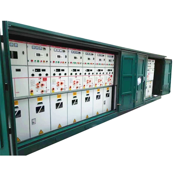
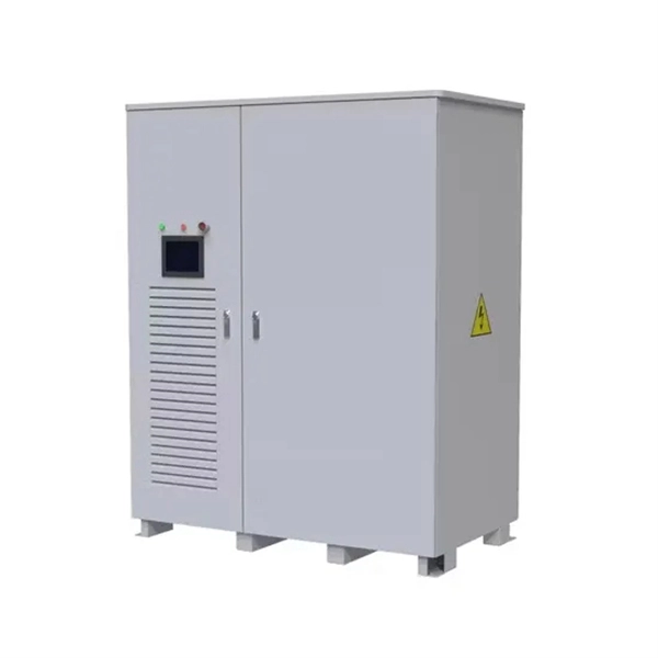
Residual current devices (RCDs) at both the tertiary (equipment-level) and secondary (zone-level) stages. Ensures safe disconnection in case of faults or leakage currents. A distribution box is installed under the main distribution box, and a switch box is installed under the distribution box. These boxes feature bottom entry and exit cables, front-opening doors, and main busbars connected with copper strips for optimal contact. They also include metering systems, ensuring. In a newly constructed residential area, a 10kV power line is introduced into the substation. After stepping down the voltage through the transformer's low-voltage side (0. 4kV), power distribution is achieved through three levels of distribution boxes: the main distribution board, secondary. Equipment inside usually includes isolating switches, circuit breakers, and residual current devices (RCDs). Supplies power to specific buildings or floors. It is specially designed for the special situation of the project construction site and meets the relevant construction power specifications and standards of the. A distribution board (also known as panelboard, circuit breaker panel, breaker panel, circuit breaker, electric panel, fuse box or DB box) is a component of an electricity supply system that divides an electrical power feed into subsidiary circuits while providing a protective fuse or circuit.
[PDF]
An optical power meter (OPM) works by converting light energy into electrical energy using a photodiode sensor. When light from a fiber optic cable hits the sensor, it generates a small electrical current related to the light's strength. Optical power meters are a key element in the optimization and maintenance of such optical networks and of their components. In this article, learn: What is an optical power meter? An optical power meter (OPM) measures the power levels of light signals in devices that transmit data or power using. An optical power meter (OPM) is a device used to measure the power in an optical signal. The term usually refers to a device for testing average power in fiber optic systems. It measures the optical power transmitted through a fiber, helping to verify if the light signal is strong enough for communication. Beginners may find it complex, but understanding its function makes it. This article provides a comprehensive overview of optical power meters, instruments used to measure the power of light beams. It details the main components, including sensor heads and display units, and explains the two primary sensor technologies: robust thermal sensors for high powers and. A fiber-optic power meter is a quantitative measurement instrument, not a diagnostic tool by itself.
[PDF]
Picking up the best router for fiber internet isn't just about going to the market and choosing one of the best wireless routers. Instead, you need to carefully look at its specs, performance, and the type of securit.
[PDF]