One-line diagrams and detailed network data (lines, transformers, buses). Short-circuit models, including fault current calculations under various system configurations. Protective relay settings and coordination curves. Historical. presentation of protection and control relaying. The report will identify methodology behind these practices, present issues raised by the integration of microprocessor relays and the internal logic and external communication configurations, ying. Schematic diagrams of protection relays are essential tools for power engineers in the power generation, transmission, and distribution industry. This includes AC schematics and DC schematics and diagrams that prominently feature relaying. There are other equally important types of drawings that are not the subject. Power System Protective Relays: Principles & Practices Presenter: Rasheek Rifaat, P. Eng, IEEE Life Fellow IEEE/IAS/I&CPSD Protection & Coordination WG Chair Jacobs Canada, Calgary, AB rasheek. com IEEE Southern Alberta Section PES/IAS Joint Chapter Technical Seminar - November 2016. Recognized under 2(f) and 12 (B) of UGC ACT 1956 (Affiliated to JNTUH, Hyderabad, Approved by AICTE - Accredited by NBA & NAAC – 'A' Grade - ISO 9001:2015 Certified) Maisammaguda, Dhulapally (Post Via. Kompally), Secunderabad – 500100, Telangana State, India To introduce all kinds of circuit.
[PDF]
The article provides an overview of protective relaying principles and their applications for high-voltage power system components. It covers the protection methods for generators, transformers, buses, and transmission lines using various relay types to detect and. Protective relaying is the backbone of fault detection and system isolation in As transmission systems grow increasingly complex with integration of renewables and smart technologies, the design, configuration, and application of protective relays have become more critical than ever. This article. tensify their search for reductions in capital investment and operating expenses. Faced with the continuing demand for more and more power in an environmentalist era, many operating companies are seeking, among other things, a means for supplying eliable power with fewer transmission lines and. SIPROTEC 7SD82 provides compact, cost-optimized line differential protection for medium- and high-voltage systems. It ensures safety with 3-pole tripping in 19 ms and high availability via conformal coating. The modular SIPROTEC 7SD86 is specifically designed for line differential protection of. Still deciding? Get samples first! Order sample Still deciding? Get samples first! Order sample. In HV (High Voltage) and MV (Medium Voltage) substations, relay protection safeguards critical assets such as transformers, circuit breakers, and lines. Effective relay protection depends on.
[PDF]
Download Sample Report Now: Global Protective Relays Market Size, Share, Trends & Forecast 2026-2034 The following comparison highlights how leading players differentiate across scale, strategy, and regional dominance. Protective relays are electrical devices that are designed to detect abnormal conditions in power systems and isolate the affected part of the system. Insight: Global leaders dominate through scale, while niche innovators gain. These companies offer protective relay devices for electrical systems, protecting them from overloads, short circuits, and other electrical faults. *Disclaimer: List of key companies in no particular order Latest Company Updates: October 2023- The PJM Board of Managers has permitted some. Over Current Relay (OCR): Operates when the current value at the location where the protective relays are installed exceeds the set value. There are two types of elements that trigger the overcurrent protective relays: dimensional elements and instantaneous elements. The dimensional element. The global protective relay market is expected to reach USD 3. 9 billion by 2030, up from an anticipated USD 2. 7% over the forecast period. The shift from traditional relays to advanced, software-driven systems in protective relays brings enhanced reliability. Moreover, according to Consegic Business Intelligence, Protective Relay Market size is estimated to reach over USD 5,093. 8% from 2025 to 2032.
[PDF]
Protection is accomplished by application of a definite time overcurrent option. Current setting is greater than full load current but is lower than the motor starting current. Should a motor stall whilst running, or fail to start, due to excessive. When a motor starts, it can draw 6-8 times its full-load current for a brief period, creating significant challenges for circuit protection, voltage regulation, and system capacity planning. Understanding motor starting characteristics is essential for proper breaker sizing, motor protection relay. These time-overcurrent elements support the IEC and U. (IEEE) time-overcurrent characteristics. Electromechanical disc reset capabilities are provided for all time-overcurrent elements. protection and fault clearance in abnormal situations. The main features of the motor relay include thermal overload protection, motor start-up time supervision, locked rotor protec ion, and protection against too frequent motor starts. Addi ionally, differential protection can also be included. In order to prevent damage to the contactor, the maximum peak let-through current (Ip ) and maximum clearing energy (I2t) (amps2 seconds) of the fuse must be less than the equivalent ratings for the contactor. The clearing time and let-through characteristics of the fuse must be considered when.
[PDF]
Electromechanical protective relays at a hydroelectric generating plant. The relays are in round glass cases. The rectangular devices are test connection blocks, used for testing and isolation of instrument transformer circuits.OverviewIn, a protective relay is a device designed to trip a when a is detected. The first protective relays were electromagnetic devices, relying on coils operating on moving par. Electromechanical protective relays operate by either, or. Unlike switching type electromechanical with fixed and usually ill-defined operating voltage thresholds. Electromechanical relays can be classified into several different types as follows: "Armature"-type relays have a pivoted lever supported on a hinge or knife-edge pivot, which carries a moving contact. These relays may.
[PDF]
Earth fault protection based on measured or calculated residual current values: If a breaker fails to be triggered by a tripping order, as detected by the non-extinction of the fault current, this backup protection sends a tripping order to the upstream or adjacent breakers. In electric power systems and industrial automation, ANSI Device Numbers can be used to identify equipment and devices in a system such as relays, circuit breakers, or instruments. The device numbers are enumerated in ANSI / IEEE Standard C37. 2 Standard for Electrical Power System Device Function. In North America protective relays are generally referred to by standard device numbers. ANSI IEEE Standard Device Numbers are below: (the more commonly used ones are in bold) 86T is a Lockout Relay for a. The ANSI standard device numbers ( As per ANSI/IEEE standard C37. 2) are used in the design of an electrical power system. The list of ANSI device numbers with their acronyms is as given below. Save my name, email. The protection and control devices in electrical equipment can be referred to by numbers, with appropriate suffix letters when necessary, according to the functions they perform. Even in those parts of the world where IEC standards are predominate, the use of ANSI numbering. There are two methods for indicating protection relay functions in common use. The functions are supplemented by letters where amplification of the function is required. The other is given in IEC 60617 and uses.
[PDF]
Relays may be fitted with a "target" or "flag" unit, which is released when the relay operates, to display a distinctive colored signal when the relay has tripped.OverviewIn, a protective relay is a device designed to trip a when a is detected. The first protective relays were electromagnetic devices, relying on coils operating on moving par. Electromechanical protective relays operate by either, or. Unlike switching type electromechanical with fixed and usually ill-defined operating voltage thresholds. Electromechanical relays can be classified into several different types as follows: "Armature"-type relays have a pivoted lever supported on a hinge or knife-edge pivot, which carries a moving contact. These relays may.
[PDF]
In electrical engineering, a protective relay is a relay device designed to trip a circuit breaker when a fault is detected. : 4 The first protective relays were electromagnetic devices, relying on coils operating on moving parts to provide detection of abnormal. The rectangular devices are test connection blocks, used for testing and isolation of instrument transformer circuits. Its main purpose is to safeguard electrical equipment like transformers, generators, and transmission lines from damage due to. Eaton's protective relays provide you with unique microprocessor-based devices that eliminate unnecessary trips, mitigate arc faults, protect motors and breakers, and provide system information to help you better manage your system. Our predictive diagnostic solutions include non-destructive testing. Protective Relay Definition: A protective relay is an automatic device that senses abnormal conditions in electrical circuits and triggers actions to isolate faults. Types of Protective Relays: Protective relays are categorized by their mechanism (electromagnetic, static, mechanical) and function. Combines protection, sensors, control power, and circuit breaker in a single package Typically added to a breaker close circuit to prevent accidental reclosure after a trip. Three fundamental components required for each circuit breaker. This prevents damage to equipment, reduces downtime, and safeguards.
[PDF]
Below is a list of best universities in the United States ranked based on their research performance in Firefighting and Fire Science. Explore the best colleges with fire protection and prevention degrees. Read more on how this ranking was calculated. A graph of 221K citations received by 5. 06K academic papers made by 48 universities in the United States was used to calculate publications' ratings, which then. Looking for colleges with a Fire Protection Major? See a list of colleges with Fire Protection here to evaluate admissions data, tuition, rankings and more. Access exclusive rankings for colleges and universities around the country. Our AI model can make mistakes. Double check important details. What's on this page: * Degree-Level Rankings Your choice of fire. The educational requirements for a protective relay technician are a combination of high school diploma, certificate, and associate degree. According to the data, a certificate in a relevant field is held by 50. 33% of protective relay technicians, while 39. 1% have an associate degree. Fire protection and safety technology majors are the most popular in California (60 schools), North Carolina (23 schools), Florida (19 schools), and Texas (13 schools). The best protection.
[PDF]
This connection is used to driving a Neutral Displacement Relay for detection of Earth fault in non-effectively earthed systems. Earth faults causes displacement of system neutral, particularly in the case of unea.
[PDF]

The total interruption time for a modern high-voltage SF6 circuit breaker is typically between 40 to 60 milliseconds on a 50Hz grid, or 2 to 3 cycles. This is the total time from the trip signal to the final arc extinction, a critical parameter for grid safety. While knowing the total time is a. When a SF6 circuit breaker (CB) hits its critical low pressure, its fault interrupting capability can be compromised. Most TOs protect against this by either auto-opening the CB prior to reaching the critical low-pressure level or by blocking the CB from tripping (when it reaches the critical. The protected zone is defined and limited by different things depending on the protection function. Definite time delay means that the protection operate time dose not change or depend on the fault type or the fault current magnitude. Instead of oil, air, or a vacuum, a sulfur hexafluoride circuit breaker uses sulfur hexafluoride (SF 6) gas to cool and quench the. Page 1 Content Instruction Manual circuit- breaker GL317 With spring operating mechanisms FK3- 4 Administrator First issue Compiled by Approved by 19- 11- 2012 J. Texier Imagination at work Grid Solutions 04- 2017 D1736EN/03 GE Information 1/10. Page 2 Content Instruction Manual This. A comparison of the time it takes protective devices to operate when certain levels of normal or abnormal current pass through them. LV circuit breaker ratings.
[PDF]

A protection relay tripping circuit connects relays to breakers for fast fault isolation. Key components include trip/close coils and anti-pumping relays. Proper design, testing, and maintenance ensure reliable overcurrent, differential, and auto-reclosing protection in power. The protection relay tripping circuit refers to the critical electrical control loop that executes trip/close commands from protective relays to circuit breakers, ensuring rapid fault isolation in power systems. Essential. Electromechanical protective relays at a hydroelectric generating plant. The relays are in round glass cases. In electrical engineering, a protective relay is a relay device. A protective relay is an intelligent electrical device designed to detect faults in power systems and initiate corrective actions such as tripping a circuit breaker. Its main purpose is to safeguard electrical equipment like transformers, generators, and transmission lines from damage due to. By definition, a protective relay is a switchgear device that detects faults and initiates the circuit breaker operation to isolate the problematic component of the system. Electrical values are measured by these relays to determine abnormal circumferences of a circuit. It functions as a watchdog by constantly surveying multiple system components including voltage, current, frequency, and phase angle.
[PDF]
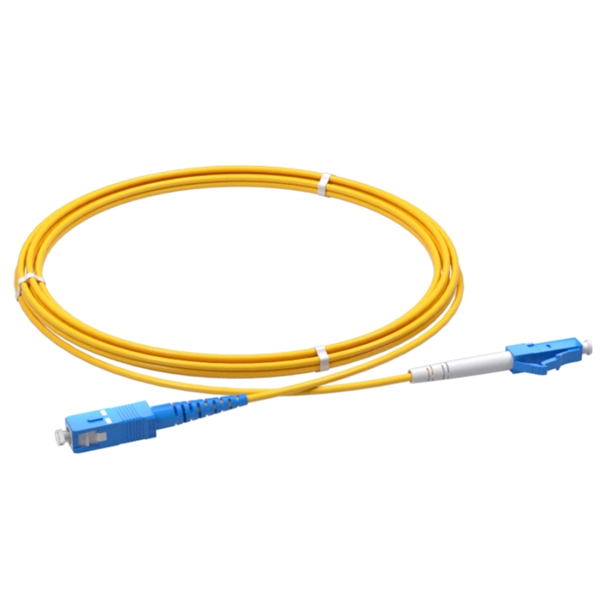
Temukan daftar Supplier, Pabrik, Importir, Distributor dan Toko Kabel Patch Cord untuk wilayah Indonesia . Update setiap hari, harga kompetitif dan layanan terpercaya. High performance and high quality connectors cable assembly are required for next generation optical networks to assure long term reliability for demanding applications such as FTTx, DWDM, 100G, CATV and etc. The connector assemblies are IEC, Telcordia and RoHS compliant. The termination passed. Prima Akses Digital Indonesia, is a Indonesian local company specialized in fiber optic product development and solution service for network infrastructure. Prima Akses Digital Indonesia, established in 2020, is supported by several partner companies and management which have been experienced in.
[PDF]

The standard industry practice is to set overload relays at 125% of the motor's nameplate Full Load Ampere (FLA) rating. Plug Setting Multiplier (PSM) indicates how many times the determined relay secondary current (typically the CT secondary) exceeds the relay pickup (plug) current. It is the key quantity utilized in IDMT (inverse definite minimum time) curves to calculate the basic operating time. PSM (Plug Setting. An overload relay is a crucial device for motor control, designed to prevent motors from overheating or suffering winding damage due to excessive current. Motor overload relays protect against sustained overcurrent conditions that cause dangerous overheating, insulation breakdown, and premature. Overload relays protect motors and equipment from thermal damage caused by prolonged overcurrent conditions. IEC 60255 defines standards, formulas, and performance requirements, enabling accurate calculations and real-world applications. How is the overload relay current calculated? Why include. Setting motor overload relays correctly is critical for protecting AC induction motors from sustained overcurrent conditions while avoiding nuisance trips during normal starting transients. This occurred when the relay F was set at 1. The complaint was that the relay tripped instantly on overload when the thermal damage curve show plotted for a specific current that was less t an.
[PDF]
In all electrical relays, the moving contacts are held in place by a continuous force, known as the controlling force. This force keeps the contacts in their normal positions and can be gravitational, spring.
[PDF]