Trim solid or stranded wire to length and insert into clamp-style terminals. Tighten with a screwdriver. Tug on all connections to make sure they are secure. Close up electrical boxes. Turn on the power and check your work. Learn how to wire a distribution box step by step! This video shows real on-site footage of electrical installation, demonstrating safe and standardized wiring methods used by professionals. Make sure the power's off using a non-contact voltage tester or multimeter. One final tip: Get into the habit of making connections in this. This guide provides step-by-step instructions for connecting a distribution box and highlights key factors to consider during installation. What Is a Distribution Box? A distribution box, also known as an electrical distribution board, is a critical component in electrical systems. It serves as a. Material preparation: Prepare the required circuit breakers, wires, wiring ties and other materials, and ensure that they meet the design drawings and installation requirements. Choose the right box based on environment (indoor/outdoor), load capacity, and durability. Check for proper IP/NEMA ratings and material quality. Beginning of dialog window. Escape will cancel and close the window. This modal can be closed by pressing the Escape key or activating the close button.
[PDF]
This comprehensive guide provides step-by-step instructions for sizing electrical cables in accordance with Australian Standard AS/NZS 3008. Electrolytic Tough Pitch (ETP) : The workhorse for most applications - 99. 9% pure with oxygen molecules peppered throughout the structure. Offers optimal balance of conductivity and cost Oxygen-Free Copper (OFC) : Created in oxygen-free environments, eliminating oxide impurities. Has marginally. Selecting the correct cable size is not just about electrical efficiency—it is a critical safety requirement. Under-sized cables lead to insulation failure, fire hazards, and significant equipment damage. Whether you're an electrical engineer, contractor, or student, this resource will help you master the essential calculations for selecting the. The National Electrical Code (NEC) provides clear guidelines for ground wire sizing through Table 250. 122, but understanding how to apply these requirements correctly can make the difference between a safe installation and a costly code violation. Proper grounding conductor sizing is critical for. Professional electrical wire sizing tool based on National Electrical Code (NEC) standards. Calculate proper wire gauge, voltage drop, and ampacity for safe electrical installations. Input your electrical parameters to get accurate wire size.
[PDF]
This post is a step-by-step detailed installation guide on how to run wires for security cameras to help you install security camera wiring for both indoors and outdoors. Proper wiring is crucial to ensuring that your security cameras function effectively and provide clear, uninterrupted footage. How to connect your cameras and recorder to provide power and a video feed, including for remote viewing via smartphones and computers. We always recommend wired systems when possible. We offer two different types of wired security camera systems -. There are two different ways to install security camera wiring: POE security camera wiring and wireless security camera wiring. Whether you're securing your home or business, the quality and installation of your camera wiring play a crucial role in ensuring consistent, high-quality video feeds. In this guide, we. This article provides a detailed principle explanation of 3R methods (reamplification, reshaping, and retiming) to reach the extension of passive optical networks. The second part of the article focuses on optical amplifiers, their advantages and disadvantages, deployment, and principles. We. In this step-by-step guide, we will walk you through the process of wiring your 2 wire security camera, providing you with a clear understanding of the necessary steps and a helpful diagram to refer to.
[PDF]
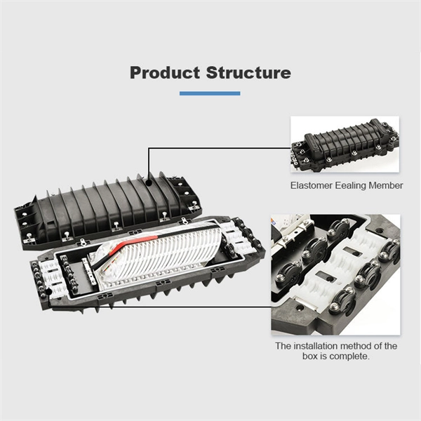
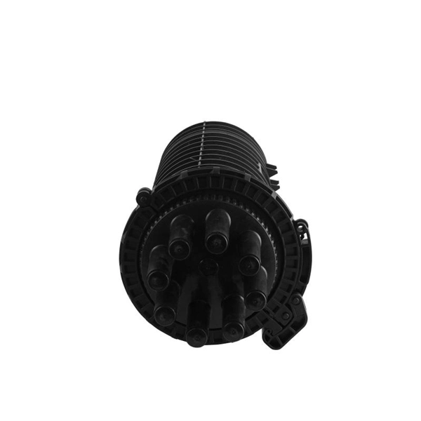
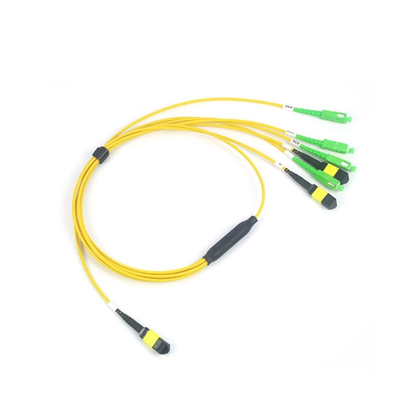
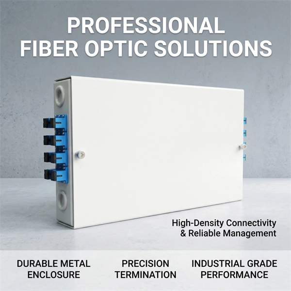
Proper fiber optic termination is a crucial process for ensuring the reliability, performance, and long-term durability of any fiber optic network. The process of fiber optic cable termination is the essential act of connecting fiber optic cables to devices, patch panels, or other. Fiber optic joints or terminations - where cables are terminated - are made two ways: 1) connectors that mate two fibers to create a temporary joint and/or connect the fiber to a piece of network gear (left) or 2) splices which create a permanent joint between the two fibers (right). Thus, you will put the cable across the points, stretch it to determine length, cut it accordingly, and place the connector on each end. After that, the patch panel attaches to it. Each cable has a connector attached. A. Once fiber optic cables have been successfully placed, we can focus on managing the ends of the fibers. This process depends on the project's needs and identifying a solution that aligns with the current situation. We can make suggestions that typically benefit the current circumstances and result. Where copper twisted pairs tend to terminate with an RJ45 plug, fiber optic connectors come in all sorts of shapes and sizes, with all manner of different use cases in mind. An optical fiber connector is used to join optical fibers where a connect/disconnect capability is required.
[PDF]
In this video, we'll walk you through the process of wiring a home distribution box with a detailed connection diagram. Whether you're an electrician or a DIY enthusiast, this guide will help you understand the basics of home electrical distribution. What is Distribution Board? Distribution board. An electrical panel box, also known as a breaker box or a distribution board, is a crucial component of any electrical system. It serves as a central hub for distributing electricity throughout a building, ensuring that power is delivered safely and efficiently to all the required locations. Distribution Board or DB is an electricity supply system or a common enclosure that distributes the electrical power feed into subcircuits. It includes isolator, RCCB (Residual current circuit breaker) or RCD (Residual-current device) devices, protective fuses or MCB's (Miniature Circuit Breaker). A distribution board or distribution box is where the main power supply is distributed to multiple loads. And all the switching and protective devices are installed in the distribution box. Single Phase Distribution Box generally consists of Double Pole MCBs, Single Pole MCBs, and RCCBs. In the following tutorial, we will show how to wire 120V single-phase and 240V split-phase circuit breakers and loads inside a residential main panel. The figure below shows a typical breaker panel used for 120V and 240V circuits. Three conductors enter the main panel from the energy meter and main.
[PDF]
Follow a clear step-by-step process: install the ground rod deeply, connect the grounding wire securely, attach it to the panel's ground bus bar, and test the system with proper equipment. Installed correctly, grounding wire can prevent electrical shocks or fires at homes or in offices. This guide reviews the basics of electrical grounding, how to safely ground wiring and how to check if wire is grounded. SHOP GROUNDING WIRES NOW Why Does Wiring Need to be Grounded? Install grounding. However, for experienced DIYers, this guide provides a detailed, step-by-step approach to ensuring your circuit breaker box is properly grounded, enhancing electrical safety grounding throughout your home. It. Section 250. For grounded systems, the NEC requires you to perform all of the following: electrical system grounding, electrical equipment grounding, electrical equipment. Drive a ground rod into the earth and attach a grounding wire to the main electrical panel to add grounding to an existing panel. Install new outlets with a continuous grounding connection to the grounding rod. In this post, I'll go through why every electrical panel should be grounded, what ground. The correct connection method of Distribution box grounding wire mainly includes the following steps: 1. Find the grounding bar or PE bar Open the distribution box and find the position marked with the grounding plate or PE letter.
[PDF]
In this video, we'll walk you through the process of wiring a home distribution box with a detailed connection diagram. Whether you're an electrician or a DIY enthusiast, this guide will help you understand the basics of home electrical distribution. more Welcome to our channel! In this video. Understanding the wiring diagram of an electrical panel box is essential for electricians and homeowners alike, as it allows them to troubleshoot any electrical issues, carry out repairs, or make additions to the system. The electrical panel box wiring diagram provides a visual representation of. A distribution board or distribution box is where the main power supply is distributed to multiple loads. And all the switching and protective devices are installed in the distribution box. Single Phase Distribution Box generally consists of Double Pole MCBs, Single Pole MCBs, and RCCBs. Connect the two hot conductors (typically black and red) to the line terminals of the main disconnect switch. Tighten each lug to 250 inch-pounds using a torque wrench. What is Distribution Board? Distribution board.
[PDF]
Thinner cables can be utilized to connect the control switch to the relay; this saves space, weight, and cost. The same voltage and current ratings as other types of switches, such as mechanical switches, do not limit relays. This handbook covers the code of practice in protection circuitry including standard lead and device numbers, mode of connections at terminal strips, colour codes in multicore cables, dos and donts in execution. Also principles of various protective relays and schemes including special protection. A control relay is an electrically operated switch that enables current to flow through a coil that closes or opens the switch. Relays use a small current to control a larger current, making them ideal for controlling high-power devices such as motors, lights, valves, and sensors. When a relay contact is open, this will switch power ON for a circuit when the coil is activated. You'll connect a low-power control circuit to the relay's coil (terminals 85 and 86), which then flips a switch for a separate, high-power circuit running through the. Electrical protection relay has two type protecton as HT panel protection and LT panel protection. HT panel protection relay. The HT power supply is received from GO switch and distributed to the. The rectangular devices are test connection blocks, used for testing and isolation of instrument transformer circuits. : 4 The first protective relays were electromagnetic.
[PDF]
Because the detecting distances range from a couple inches to several meters, adjustment during installation is incredibly easy. Detection is possible even for small targets. Retro-reflective models detect the amount of light returned from a reflector installed opposite of the. Fine spot lens NF-DA03 and coaxial diffuse Fiber-OpticCable NF-DK21 enables ø0. The NF-DA06 comes with a small spot lens where sensing distance and spot size can be adjusted through the amount of fiber inserted. It is possible to change the spot size between ø0. 9 mm with a. Optical fiber sensors (OFSs) have emerged as essential tools in the monitoring of physical, chemical, and bio-medical parameters in harsh situations due to their high sensitivity, electromagnetic interference (EMI) immunity, and long-term stability. However, the current literature contains. A fiber-optic sensor is a sensor that uses optical fiber either as the sensing element ("intrinsic sensors"), or as a means of relaying signals from a remote sensor to the electronics that process the signals ("extrinsic sensors"). Fibers have many uses in remote sensing. Depending on the. There are several types of fiber optic sensors. Detection methods include thrubeam, reflective, retro-reflective, and definite-reflective. Thrubeam models include a transmitter and receiver installed opposite each other.
[PDF]
The Optical Time Domain Reflectometer (OTDR) is useful for testing the integrity of fiber optic cables. It can verify splice loss, measure length and find faults. in cable TV, LAN, metropolitan networks or long-haul. Ensure the integrity of your fiber optic network with an Optical Time Domain Reflectometer (OTDR). OTDR testing analyzes fiber optic cable performance from end to end by testing components along the cable, including connection points, bends, and splices. It injects a series of optical pulses into the fiber and analyzes the backscattered signal based on time, enabling a detailed view of the. 15 EXFO Inc. No part of this publication may be reproduced, stored in a retrieval system or transmitted in any form, be it electronically, mechanically, or by any other means such as photocopying, recording or otherwise, without the prior writt eved to be accurate and reliable. From a single end of the link, it can determine the magnitude and location of loss, detect reflections, and visualize events along the fiber. An OTDR injects a series of optical.
[PDF]
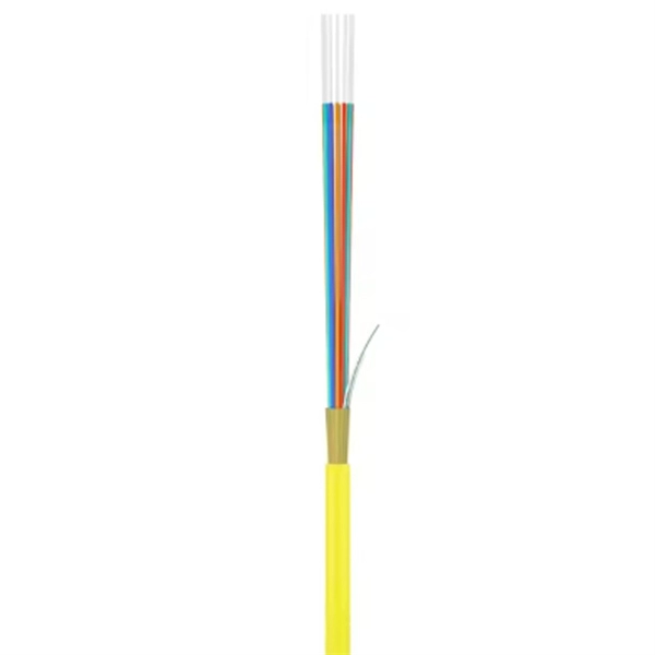
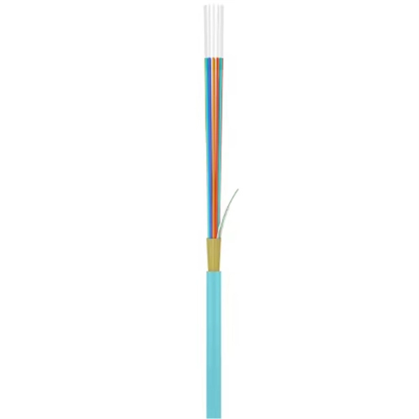
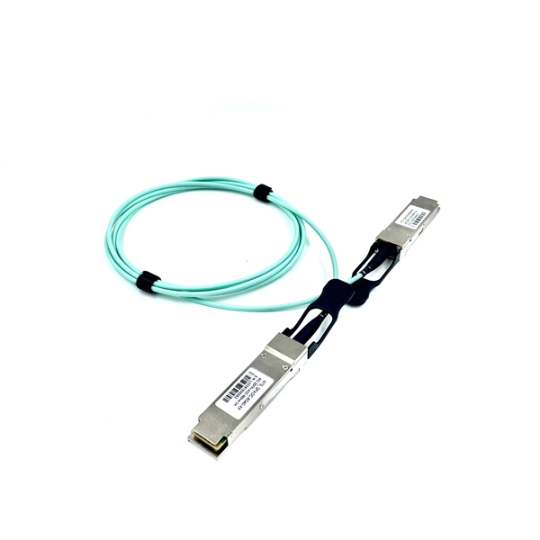
Fiber optic cable can be run anywhere from 300 meters up to 80 kilometers (roughly 50 miles) depending on the cable type, transceiver used, and network standard. For most enterprise or data center applications using multimode fiber, the practical limit sits between 300 m and 550 m. Fiber optic cables are the backbone of modern communications, enabling high-speed data transfer over vast distances. Unlike traditional copper cables, fiber optic cables use light to transmit data, resulting in faster speeds and greater bandwidth capabilities. However, fiber optic cable performance. With ideal conditions and amplification, optical fiber can transmit petabit speeds globally, but real-world limits depend on fiber type and network design. Single-mode. Fiber optic transmission distance varies based on fiber type, environmental conditions, and equipment selection. This guide explores the key factors affecting fiber optic transmission distance and provides practical selection guidelines for a stable and cost-effective network deployment. Dispersion. General Symmetric cable pairs Land coaxial cable pairs Submarine cables Free space optical systems G. 649 Optical fibre cables G. 659 Characteristics of optical components and subsystems Characteristics of optical systems G. Attenuation is the progressive loss of signal strength that occurs as light travels through the fiber. The greater the distance, the greater.
[PDF]
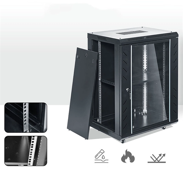
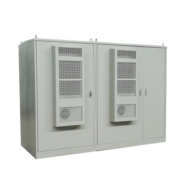
This chart guides how close workers can safely get to energized equipment based on system voltages and other factors, ensuring compliance with safety standards such as NFPA 70E. A distribution box, also known as a distribution board or panel, is the central unit that distributes incoming electrical power to various circuits. Each outgoing line can be individually. Working space: The front clearance, side clearance, and height clearance requirements for electrical equipment that provide a safe area for maintenance, inspections, and other work. Dedicated space: The space equal to the width and depth of electrical equipment in addition to the space extending. The National Electrical Code (NEC) provides comprehensive safety standards for electrical installations, including requirements for electrical panels (main service panels and subpanels or breaker box). NEC Article 408 covers switchboards, switchgear, and Panelboards installation and applications. Electrical clearances set the minimum safe distances for panels, overhead lines, pools, and buried wiring — and ignoring them has real consequences. They would have done better to use an LB or a gutter. The problem is the box has a rated fill and the wire has a bend radius. Maintaining a safe working distance from energized parts in electric power systems is critical to preventing electrical.
[PDF]
Generally, standard trays require supports every 6 to 10 feet, while heavy-duty, long-span trays can handle distances of up to 20 feet between supports. To determine the proper spacing, consult the manufacturer's load capacity chart, which accounts for the total weight of the. The following are a few points to consider when dealing with cable tray and the National Electrical Code. This is a description of how to select, install, and support these metal or plastic frames, on which electrical wires are installed. You should consider it as a series of instructions that make the buildings resistant to. Support spacing for cable trays must align with the manufacturer's instructions, as outlined in NEC 392. This spacing is crucial for adequate maintenance access, ease of inspection, and ensuring proper airflow for effective heat dissipation. It also helps reduce the risk of. In this installment of our Code Corner series, Ryan Mayfield focuses on the 2023 National Electrical Code (NEC) changes concerning cable trays, particularly section 690. Historically, the NEC has allowed cable trays, but has lacked specific guidelines for sizing conductors and using smaller. This guide covers the critical steps, from selecting the right electrical cable tray and performing accurate cable fill calculations to managing a safe cable pull through and ensuring all bonding and grounding requirements are met. For licensed electricians, mastering these principles is essential.
[PDF]
This video shows real on-site footage of electrical installation, demonstrating safe and standardized wiring methods used by professionals. more Learn how to wire a distribution box step by step! This video shows real on-site footage of. Hey, in this article we are going to see the Single Phase Distribution Box Wiring Diagram and Connection Procedure. A distribution board or distribution box is where the main power supply is distributed to multiple loads. And all the switching and protective devices are installed in the. Box installation: Make sure that Distribution box has been correctly installed and fixed. Material preparation: Prepare the required circuit breakers, wires, wiring ties and other materials, and ensure that they meet the design drawings and installation requirements. Location determination:. In this video, we'll walk you through the process of wiring a home distribution box with a detailed connection diagram. Whether you're an electrician or a DIY enthusiast, this guide will help you understand the basics of home electrical distribution. What Is a Distribution Box? A distribution box, also known as an electrical distribution board, is a critical component in electrical systems. It serves as a.
[PDF]
This video goes over common types of connectors, their respective adapters, and how to properly connect and disconnect them. For your safety, it is always advised to follow proper fiber optic handling techniques and utilize the correct protective gear when performing. Fiber optic adapters, also known as couplers, play a crucial role in fiber optic networks by providing a connection point between two fiber optic connectors. They enable seamless and reliable optical signal transmission between different fiber optic cables, connectors, or devices. In this tutorial. Proper connection of fiber optic cables is essential to harness these benefits fully, as even minor errors can lead to significant performance issues like signal loss. more Are you interested in seeing how fiber optic connectors get. Vigitron's Vi5004 is a 4-port fiber optic media convertor that enables Ethernet signals to be transmitted over fiber optic cables. It enable UTP Ethernet to connect to fiber to meet long distance transmission requirement or where fiber is already installed. Why Use Fiber Optic Internet? Before diving into the setup, let's quickly recap why fiber optics are worth the effort: Lightning-fast speeds (up to 1 Gbps or higher). Low latency for.
[PDF]