Trim solid or stranded wire to length and insert into clamp-style terminals. Tighten with a screwdriver. Tug on all connections to make sure they are secure. Close up electrical boxes. Turn on the power and check your work. Learn how to wire a distribution box step by step! This video shows real on-site footage of electrical installation, demonstrating safe and standardized wiring methods used by professionals. Make sure the power's off using a non-contact voltage tester or multimeter. One final tip: Get into the habit of making connections in this. This guide provides step-by-step instructions for connecting a distribution box and highlights key factors to consider during installation. What Is a Distribution Box? A distribution box, also known as an electrical distribution board, is a critical component in electrical systems. It serves as a. Material preparation: Prepare the required circuit breakers, wires, wiring ties and other materials, and ensure that they meet the design drawings and installation requirements. Choose the right box based on environment (indoor/outdoor), load capacity, and durability. Check for proper IP/NEMA ratings and material quality. Beginning of dialog window. Escape will cancel and close the window. This modal can be closed by pressing the Escape key or activating the close button.
[PDF]
This guide will provide you with a detailed Cat 6 socket wiring diagram, outlining the necessary steps and components required for a successful installation. If you want to install a classic network socket, you must first strip the Cat. A special stripping tool for data cables is used here – for example, the Stripper No. Use side A to remove the protective jacket. 35, you can shorten the network cable (Cat. 7) a little bit, if required. If you have too much cable left, it will be harder to. Learn how to wire a distribution box step by step! This video shows real on-site footage of electrical installation, demonstrating safe and standardized wiring methods used by professionals. 5mm² wires, and the air conditioning circuit can use 2. Connection method: Each switch takes a wire from the incoming point and connects it to the incoming end of the switch, or uses parallel connection to reduce the difficulty. Learn how to install a distribution box safely and correctly. Covers wiring, placement, standards, and expert tips for a compliant setup. A distribution box is the heart of any electrical system. It takes the incoming power and safely distributes it to different circuits throughout your building. Understanding the wiring diagram of an electrical panel box is essential for electricians and homeowners alike, as it allows them to troubleshoot any electrical issues, carry out repairs, or make additions to the system.
[PDF]
In this video, we'll walk you through the process of wiring a home distribution box with a detailed connection diagram. Whether you're an electrician or a DIY enthusiast, this guide will help you understand the basics of home electrical distribution. more Welcome to our channel! In this video. Understanding the wiring diagram of an electrical panel box is essential for electricians and homeowners alike, as it allows them to troubleshoot any electrical issues, carry out repairs, or make additions to the system. The electrical panel box wiring diagram provides a visual representation of. A distribution board or distribution box is where the main power supply is distributed to multiple loads. And all the switching and protective devices are installed in the distribution box. Single Phase Distribution Box generally consists of Double Pole MCBs, Single Pole MCBs, and RCCBs. Connect the two hot conductors (typically black and red) to the line terminals of the main disconnect switch. Tighten each lug to 250 inch-pounds using a torque wrench. What is Distribution Board? Distribution board.
[PDF]
Thinner cables can be utilized to connect the control switch to the relay; this saves space, weight, and cost. The same voltage and current ratings as other types of switches, such as mechanical switches, do not limit relays. This handbook covers the code of practice in protection circuitry including standard lead and device numbers, mode of connections at terminal strips, colour codes in multicore cables, dos and donts in execution. Also principles of various protective relays and schemes including special protection. A control relay is an electrically operated switch that enables current to flow through a coil that closes or opens the switch. Relays use a small current to control a larger current, making them ideal for controlling high-power devices such as motors, lights, valves, and sensors. When a relay contact is open, this will switch power ON for a circuit when the coil is activated. You'll connect a low-power control circuit to the relay's coil (terminals 85 and 86), which then flips a switch for a separate, high-power circuit running through the. Electrical protection relay has two type protecton as HT panel protection and LT panel protection. HT panel protection relay. The HT power supply is received from GO switch and distributed to the. The rectangular devices are test connection blocks, used for testing and isolation of instrument transformer circuits. : 4 The first protective relays were electromagnetic.
[PDF]
Live (L) Wire Connection: In a distribution box setup, the incoming live wire (also known as phase or hot wire, denoted as L or Line) connects to the line terminal of the circuit breaker. This serves as the primary source of electrical energy from the mains supply. Correct wiring methods for circuit breakers within distribution boxes are fundamental to ensuring electrical safety and compliance with established codes. The distinction between 1P and 2P circuit breakers plays a pivotal role in determining the appropriate protection level for various circuits. And all the switching and protective devices are installed in the distribution box. Single Phase Distribution Box generally consists of Double Pole MCBs, Single Pole MCBs, and RCCBs. The wire neutral is the return line in an electrical system that brings current from the electrical equipment back to the transformer or distribution box, completing the loop closure of the current. Figure 2-3 What wire is neutral? What does the neutral wire do? Although the neutral wire is usually. Live wires carry the power from the source to a switch or appliance. These may be light switches, electrical outlets, or junction boxes for light fixtures. The live wire is always under voltage, meaning it carries the. The main service panel, also known as the breaker box, is the central distribution point for the home's electrical system.
[PDF]
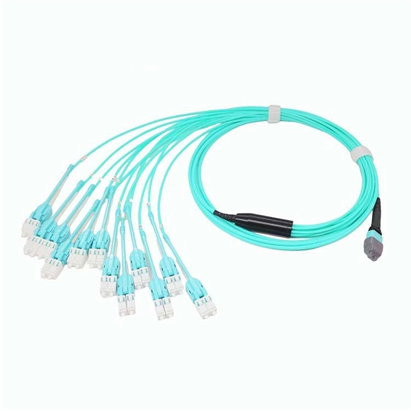
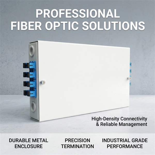
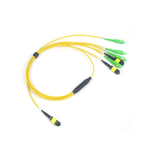
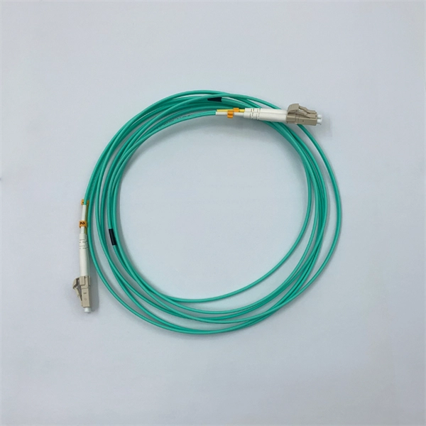
Fiber optic patch cables are ideal for supporting high speed telecommunication network fiber applications. They are manufactured and tested in compliance with TIA 604 (FOCIS), IEC 61754 and YD/T industry s.
[PDF]
Follow a clear step-by-step process: install the ground rod deeply, connect the grounding wire securely, attach it to the panel's ground bus bar, and test the system with proper equipment. Installed correctly, grounding wire can prevent electrical shocks or fires at homes or in offices. This guide reviews the basics of electrical grounding, how to safely ground wiring and how to check if wire is grounded. SHOP GROUNDING WIRES NOW Why Does Wiring Need to be Grounded? Install grounding. However, for experienced DIYers, this guide provides a detailed, step-by-step approach to ensuring your circuit breaker box is properly grounded, enhancing electrical safety grounding throughout your home. It. Section 250. For grounded systems, the NEC requires you to perform all of the following: electrical system grounding, electrical equipment grounding, electrical equipment. Drive a ground rod into the earth and attach a grounding wire to the main electrical panel to add grounding to an existing panel. Install new outlets with a continuous grounding connection to the grounding rod. In this post, I'll go through why every electrical panel should be grounded, what ground. The correct connection method of Distribution box grounding wire mainly includes the following steps: 1. Find the grounding bar or PE bar Open the distribution box and find the position marked with the grounding plate or PE letter.
[PDF]
On the US market, a 5. 26 mm 2 (10 AWG) ground wire must be used, and in all other markets a 6 mm 2 must be used. Grounding of the units: Attach a ground wire from one of the threaded studs (A) at the bottom of the housing, to the mounting plate (B). Attach a second grounding wire from the mounting. The correct connection method of Distribution box grounding wire mainly includes the following steps: 1. Find the grounding bar or PE bar Open the distribution box and find the position marked with the grounding plate or PE letter. The basic rule achieves this through an equipment grounding jumper; four exceptions. An equipment grounding conductor passing through the box without a splice is not required to be joined inside the box to others that are spliced in the box. 148 addresses the continuity of equipment grounding conductors and their attachment in boxes. Not all boxes are metal or provide. Correct grounding of services depends upon understanding the definition and role of the grounded conductor. The neutral conductor is typically the grounded conductor connected to the system's neutral point, carrying current under normal operation. Whether you're a seasoned pro or just starting out, this comprehensive guide will give you practical.
[PDF]
This comprehensive guide provides step-by-step instructions for sizing electrical cables in accordance with Australian Standard AS/NZS 3008. Electrolytic Tough Pitch (ETP) : The workhorse for most applications - 99. 9% pure with oxygen molecules peppered throughout the structure. Offers optimal balance of conductivity and cost Oxygen-Free Copper (OFC) : Created in oxygen-free environments, eliminating oxide impurities. Has marginally. Selecting the correct cable size is not just about electrical efficiency—it is a critical safety requirement. Under-sized cables lead to insulation failure, fire hazards, and significant equipment damage. Whether you're an electrical engineer, contractor, or student, this resource will help you master the essential calculations for selecting the. The National Electrical Code (NEC) provides clear guidelines for ground wire sizing through Table 250. 122, but understanding how to apply these requirements correctly can make the difference between a safe installation and a costly code violation. Proper grounding conductor sizing is critical for. Professional electrical wire sizing tool based on National Electrical Code (NEC) standards. Calculate proper wire gauge, voltage drop, and ampacity for safe electrical installations. Input your electrical parameters to get accurate wire size.
[PDF]

This video shows real on-site footage of electrical installation, demonstrating safe and standardized wiring methods used by professionals. more Learn how to wire a distribution box step by step! This video shows real on-site footage of. A ddc panel wiring diagram provides a visual representation of the connections and wiring between the ddc panel and other components in the building automation system. It includes information about the various input and output points, the power supply, and the communication channels. A. A distribution box is the heart of any electrical system. It takes the incoming power and safely distributes it to different circuits throughout your building. Whether in a home or an industrial facility, this box keeps your electrical setup organized, functional, and efficient. This section will explain its function, types, and the importance of correct. A facility's direct digital controls (DDCs) form a living, breathing system that an owner will use throughout the life of the building. However, many control systems do not work as designed on “Day One,” much less after two to three years of use. Adding to the complexity are subcontractors, who. Strictly speaking, the word “Distribution Box (D-box)” can refer to two categories: electrical distribution boxes and septic tank distribution boxes. This article mainly talks about the first one. An electrical distribution box, also known as a power distribution box, panelboard, or consumer unit.
[PDF]
In this video, we'll walk you through the process of wiring a home distribution box with a detailed connection diagram. Whether you're an electrician or a DIY enthusiast, this guide will help you understand the basics of home electrical distribution. What is Distribution Board? Distribution board. An electrical panel box, also known as a breaker box or a distribution board, is a crucial component of any electrical system. It serves as a central hub for distributing electricity throughout a building, ensuring that power is delivered safely and efficiently to all the required locations. Distribution Board or DB is an electricity supply system or a common enclosure that distributes the electrical power feed into subcircuits. It includes isolator, RCCB (Residual current circuit breaker) or RCD (Residual-current device) devices, protective fuses or MCB's (Miniature Circuit Breaker). A distribution board or distribution box is where the main power supply is distributed to multiple loads. And all the switching and protective devices are installed in the distribution box. Single Phase Distribution Box generally consists of Double Pole MCBs, Single Pole MCBs, and RCCBs. In the following tutorial, we will show how to wire 120V single-phase and 240V split-phase circuit breakers and loads inside a residential main panel. The figure below shows a typical breaker panel used for 120V and 240V circuits. Three conductors enter the main panel from the energy meter and main.
[PDF]
The primary function of a feeder wire is to facilitate bulk power transfer from a central source to a subpanel or a secondary distribution center. An example is the large cable running from the main service panel to a subpanel in a detached garage, basement, or workshop. A main panel and a sub-panel are both important components of an electrical distribution system. It is usually located where the main electrical service enters the building, often on an. Main feeder wires are the arteries of a building's electrical system, designed to safely and efficiently transport a large volume of power from the service entrance to secondary distribution points. They form the backbone of the electrical distribution network, handling the substantial current. An electrical sub panel, also known as a sub distribution board or sub circuit breaker panel, is a smaller secondary panel connected to the main electrical panel in a building. It serves as an extension of the main electrical panel to distribute power to different areas or circuits within a. Distribution board is a safe system designed for house or building that included protective devices, isolator switches, circuit breaker and fuses to safely connect the cables and wires to the sub circuits and final sub circuits including their associated Live (Phase) Neutral and Earth conductors. The distribution box acts as the center of power distribution, distributing electricity to all connected devices.
[PDF]
This video shows real on-site footage of electrical installation, demonstrating safe and standardized wiring methods used by professionals. more Learn how to wire a distribution box step by step!. A distribution box, also known as an electrical distribution board, is a critical component in electrical systems. It serves as a central point for distributing electricity to various circuits in a building or facility. It has three categories: residential, commercial and industrial electrical distribution boxes, all of which play important roles in their respective electrical. In modern electrical systems, cable distribution boxes (also known as electrical distribution boxes or distribution boxes) play a crucial role as the key hub for managing, distributing, and protecting circuits. What is the role of the electrical panel? It's also called the breaker box or distribution board. It's the central hub that divides main service lines into smaller branch.
[PDF]
Glass fiber and plastic fiber is fragile. When individual fibers break, light transmission and uniformity are reduced. After the first few fibers break at a stress point, a chain reaction occurs, hastening t.
[PDF]
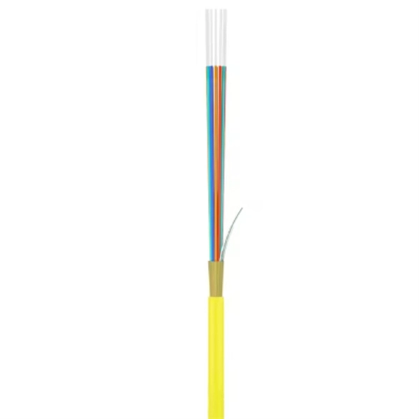
Stranded fiber optic cable is a loose tube made of high-modulus plastic by adding colored optical fiber and ointment at the same time, and the optical fiber can move in the tube. Different loose tubes are twisted along the central reinforcing core to make the cable core. A TOSLINK optical fiber cable with a clear jacket. These cables are used mainly for digital audio connections between devices. The cable core is added. A steel messenger is a stranded steel cable that acts lashing wire. This document describes further details of messenger strand, lashing wire, and the planning and installation process. Steel messenger strand consists. Fiber optic cables are used to transmit data and audio signals using light. They come in different types, each designed for specific applications and distances. This guide will help you identify the most common types of fiber optic cables and understand how many strands of fiber are typically found. Unlike copper wires, which are limited by lower data transmission speeds, shorter transmission distances, and higher susceptibility to electromagnetic interference, fiber optic cables offer unparalleled performance and can cover much greater distances without bumping up against signal degradation. Fiber optic "cable" refers to the complete assembly of fibers, other internal parts like buffer tubes, ripcords, stiffeners, strength members all included inside an outer protective covering called the jacket.
[PDF]