An optical power meter (OPM) works by converting light energy into electrical energy using a photodiode sensor. When light from a fiber optic cable hits the sensor, it generates a small electrical current related to the light's strength. Optical power meters are a key element in the optimization and maintenance of such optical networks and of their components. In this article, learn: What is an optical power meter? An optical power meter (OPM) measures the power levels of light signals in devices that transmit data or power using. An optical power meter (OPM) is a device used to measure the power in an optical signal. The term usually refers to a device for testing average power in fiber optic systems. It measures the optical power transmitted through a fiber, helping to verify if the light signal is strong enough for communication. Beginners may find it complex, but understanding its function makes it. This article provides a comprehensive overview of optical power meters, instruments used to measure the power of light beams. It details the main components, including sensor heads and display units, and explains the two primary sensor technologies: robust thermal sensors for high powers and. A fiber-optic power meter is a quantitative measurement instrument, not a diagnostic tool by itself.
[PDF]
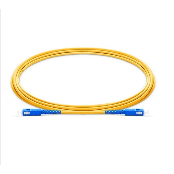
Typical rates range from $0. 00 per ft depending on terrain, access, and required precision for termination. Basic — 1,000 ft single-mode run indoors with minimal termination: Cable $0. 00/ft, Permits $150, Accessories $100. Total ≈ $2,650–$3,100. 🔥Buy Fiber Cables products online from DanounTech the best tech store📱 in Lebanon🇱🇧 | find low prices everyday, and enjoy fast delivery🚚. DanounTech | LEBANON. Fiber optic solutions (drawers, panels, connectors. ) | Fibre optic cables | !. 50-meter, 2-core single-mode fiber optic cable with APC (Angled Physical Contact) connectors, providing low-loss, low-reflection performance for high-speed data transmission. Ideal for FTTH, telecom, and network infrastructure requiring reliable duplex connectivity. Each cable features advanced fiber optic technology to deliver superior performance, low latency, and high bandwidth. Anixter is your source for Indoor/Outdoor Fiber Optic Cable products. olx Lebanon offers online local classified ads for Fiber Optic. Post your classified ad in various categories like mobiles, tablets, cars, bikes, laptops, electronics, birds, houses, furniture, clothes, dresses for sale in Lebanon.
[PDF]
In this video, we'll show you how to connect an energy meter to a distribution board (DB) safely and efficiently. energy meter connection with distribution box How to Connect an Energy Meter to Your Distribution Box Easily Steps to Properly Connect Your Energy Meter to a Distribution Box. Site/existing equip info - SFH (1 story, no basement, just crawlspace) w/ attached garage. 200A main service (Leviton panel). Covers wiring, placement, standards, and expert tips for a compliant setup. A distribution box is the heart of any electrical system. It takes the incoming power and safely distributes it to different circuits throughout your building. I am going to start digging a trench to run underground cable from a service pole breaker box to a well house; the distance is 60 feet. The breaker is a 240 V 2-pole 20-20 which will run to the well house water pump pressure switch. The present UF 2-10 AVG with ground cable runs two inches under. An electric meter box wiring diagram is a visual representation of the electrical connections and circuits involved in connecting an electric meter to the rest of the electrical system in a building. The diagram provides a clear and concise overview of how the meter is connected to the electrical. Limited the meter location from pad mount transformer for PSO. APCo and TX do not allow unistrut for installations. 7/2020 Revised Figure 15. Added wording for consistency with Section 8 of document.
[PDF]
Calibration & Repair services in Ireland. 5 day turn around with competitive pricing! View full electrical test and measurement equipment list here. is an independent calibration laboratory focused on meeting the total quality requirements of industry. Proper calibration of today's sophisticated test and measurement equipment is essential for preserving measurement accuracy, complying with international standards. Parameters covered include; Temperature, Humidity, Dewpoint, Various Gases, Pressure, Electrical, Weights & Scales, Analytical and some Specialist calibrations. Calibration is performed using the very latest Calibration Equipment/Standards & Calibration/Asset Management Software. Fast Efficient. PTM Calibration offers a wide range of services that complement our core business. We aim to be your one stop shop for all your calibration, test & measurement needs. From major blue chip companies & medium enterprises to small companies and sole traders. Including: aerospace, pharmaceuticals. OptiCal Sciences are an authorised service centre with service, repair and calibration experience and procedures for an extensive variety of models from a wide range of manufacturers.
[PDF]
The wire nut size charts below will direct you to manufacturer specific guidelines (By wire nut color and sizing). Twist-On Wire Connectors These are normally twisted on by hand and have external grooves or wings for easy handling. Twist-on connectors are usually color-coded to indicate their size or capacity. They are easy to twist on and off when needed and are commonly used in electrical wiring systems for light switches, ceiling fans, receptacles or outlets. Connectors are represented in the schematic circuit diagrams of electronic circuit designs in a number of ways. Normally the symbols are quite obvious, but they are dependent on the actual system used, and the notations used for the connector circuit symbols may vary slightly. In addition to the basic contact symbols used for the connections themse.
[PDF]
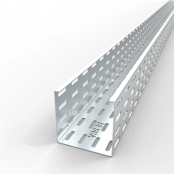
It is recommended to use tinned copper stranded wire with a minimum cross-sectional area of 4mm² for bridging, with tinned copper lugs crimped at both ends. Iron bolts welded at both ends of the cable troughs can rust and increase contact resistance. Cable tray may be used as the Equipment Grounding Conductor (EGC) in any installation where qualified persons will service the installed cable tray system. The metal in cable trays may be used as the EGC as per the limitations. Standard splice plates can often provide a safe electrical path if they are UL Classified and bolted tight. However, you must use copper bonding jumpers if the tray is painted or has expansion joints for movement. A. Cable tray wiring systems have excellent safety and dependability records. The intent of this article is to review grounding practices for cable tray. Snap Track Cable Tray Can be used as an Equipment Ground Conductor (EGC) Snap Track cable tray is UL Classified, marked with the available minimum cross sectional area and meets all requirements for use as an Equipment Ground Conductor per NEC Article 392. Standard Snap Track splices, tee's. What is best practice for terminating the ground wires within tray cable? Especially when you have a parallel tray cable feeder? For example: A parallel tray cable feeder is installed in cable tray to a 400 amp distribution panel.
[PDF]
Recommendation ITU-T L. 89 describes the general requirements and a design guide for suspension wires, telecommunication poles and guy-lines that support aerial cables for optical access networks. This Recommendation also describes loads applied to the infrastructures. Aerial infrastructure. Teleworking, online games, online medical consultations, online education - all these services are enabled by fast fi bre optic broadband networks. The intent of such a. These cables vary significantly in material, construction, and application. The core composition and number of wire strands determine their strength, flexibility, durability, and resistance to environmental factors. Understanding the different types helps in selecting the right cable for. 40. FO-VC2 JOINT USE - VERICAL MIDSPAN CLEARANCES 48. FO-GB GROUNDING AND BONDING 49. APPENDIX A - COVER SHEET / TOC 52.
[PDF]
In this video, we'll walk you through the process of wiring a home distribution box with a detailed connection diagram. Whether you're an electrician or a DIY enthusiast, this guide will help you understand the basics of home electrical distribution. What is Distribution Board? Distribution board. An electrical panel box, also known as a breaker box or a distribution board, is a crucial component of any electrical system. It serves as a central hub for distributing electricity throughout a building, ensuring that power is delivered safely and efficiently to all the required locations. This panel routes power from the utility service to every circuit while housing circuit breakers that provide overcurrent protection. Installing or replacing a load center is a complex task involving. Always begin with disconnecting the main supply before accessing any enclosure containing distribution components. This prevents arc faults and ensures safety when modifying or inspecting current paths. Inside the service housing, line conductors from the utility feed typically enter through the.
[PDF]
In this video, we'll walk you through the process of wiring a home distribution box with a detailed connection diagram. Whether you're an electrician or a DIY enthusiast, this guide will help you understand the basics of home electrical distribution. more Welcome to our. An electrical panel box, also known as a breaker box or a distribution board, is a crucial component of any electrical system. It serves as a central hub for distributing electricity throughout a building, ensuring that power is delivered safely and efficiently to all the required locations. Follow this guide for a clear and safe connection process: Before starting, always ensure the main power is turned off to avoid electrical shock. Covers wiring, placement, standards, and expert tips for a compliant setup. It takes the incoming power and safely distributes it to different circuits throughout your building. This panel routes power from the utility service to every circuit while housing circuit breakers that provide overcurrent protection. What is Distribution Board? Distribution board.
[PDF]
Your breaker box wiring includes three main wire types: black hot wires carry electricity to outlets, white neutral wires return unused power, and green ground wires prevent electrocution. The goal is to distribute circuits evenly across both L1 and L2 to keep things balanced and prevent any traydropping electrical mishaps! Now, what happens when you need more power than a single 120V line can deliver? That's where splitphase power comes in. When a circuit connects L1 to L2 (instead. A distribution board or distribution box is where the main power supply is distributed to multiple loads. And all the switching and protective devices are installed in the distribution box. Single Phase Distribution Box generally consists of Double Pole MCBs, Single Pole MCBs, and RCCBs. Wiring – Includes live, neutral, and earth wires for power distribution. Circuit Breakers – Protect the system from overloads and short circuits. Electrical switchboards can have different setups based on their. The neutral wire carries the electricity back to the power source. It completes the circuit by directing the current to a ground or busbar, normally located at the electrical panel. Once the power is “used” at the demand point, it carries it back to the panel. Note: Read my Article on 5KW Solar System Installation, you can do it yourself. Its a complete Guide. It is typically colored black, red, or another color designated for live wires.
[PDF]
Cable trays are used as an alternative to open wiring or electrical conduit systems, and are commonly used for cable management in commercial and industrial construction. In the electrical wiring of buildings, a cable tray system is used to support insulated electrical cables used for power distribution, control, and communication. Today, electrical cable trays have become an essential component in industrial and commercial construction, providing a quick, economical, and. -piece tray istypically used in applications where visual esthetics are important. It is used in a range of applications with sp nch runs from the main cable tray system to electr cal devices or other equipment. It is available with a ventilated or solid bottom. Channel tray can protect against. Cable trays support cable across open spans in the same manner that roadway bridges support traffic. Cable trays are not raceways, and are treated as a structural component of a facility's electrical system. A bridge is a structure that provides safe passage for traffic across open spans. The National Electrical Code publishes the standards for all.
[PDF]
Provides accurate and cost-effective testing methods for the optoelectronic signal testingand anomaly simulation of high-speed optical transceiver modules. The OptoBERT™ OPB04X10 is the industry's most compact, cost-effective, easy-to-use 4-channel 10Gbps electrical bit-error-ratio tester (BERT). PBT3058 is a high-performance Bit Error Ratio Tester which can be used for physical layer characterization and consistency test of high-speed serial signal. 6TBASE/CEI-224G standards and also supports PCIe rate testing ranges through extended rate. Transmitter net measurement:. Our portable and stationary provers ensure accuracy and industry compliance for flow meters on a variety of in the field applications. Available in custom configurations and max flow rates, each prover is designed to eliminate the many prover problems of the past including our Unidirectional. In high-speed digital communication systems, even the smallest bit-level error can compromise performance, reduce efficiency, or lead to costly rework. That's why Physical Layer Tech offers precision-engineered Bit Error Rate Testers (BERTs) designed to verify data transmission accuracy and ensure. Whether you are looking for the smallest handheld 100G bit error rate tester in the world for your field job, or perhaps your needs take you into the lab, VIAVI has you covered with our accurate and easy-to-use BERT equipment for any use case. · Use control board and replaceable.
[PDF]
Typical project ranges for fiber optic cable per meter span from a low of roughly $0. 65 to a high around $5. 00, depending on type, protection, and installation needs. The majority of projects cluster in the $1. 60 per meter range for standard indoor runs with simple. Fiber optic cable cost per meter varies by type (single‑mode vs multi‑mode), durability, and installation conditions. The main price drivers include cable grade, jacket material, pull tension, connectorization, and any required conduit or protection. The following coverage gives a practical price. Fiber-optic cable materials typically cost $1 to $6 per linear foot, depending on fiber count and cable type. Commercial building installations with 100-200 network drops generally range from $15,000 to $30,000. The type of fiber optic cable selected based on your requirements, length of installation, and number of fiber. Getting accurate cost estimates is crucial for winning fiber installation bids. Smart contractors know that underground vs aerial installation pricing varies wildly based on location and project conditions. We'll show actual costs for.
[PDF]